46
1.4.2 Input current
Solenoid valves are controlled via an electronic board equipped with a microprocessor.
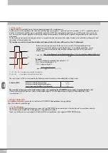
In order to ensure safe operation of the valve and reduce energy consumption, a “speed-up” control is provided, i.e. 3W is supplied to solenoid
pilot for 15 milliseconds and then power is gradually reduced to 0.25W. The microprocessor regulates, via a PWM control, the current in the
coil, which remains constant regardless of the supply voltage and temperature, thus keeping the magnetic field generated by the solenoid pilot
unchanged.
For the system power supply to be properly scaled, it is important to take into account the number of valves to be controlled simultaneously* and
the number of those already active.
*By simultaneous control is meant the activation of all solenoid pilots with a time difference less than 15 milliseconds.
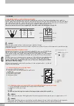
P1
P3
P2
T2
T1
15 ms
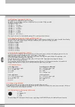
T1 = P1 + P2 + P3 = 3 simultaneously-controlled solenoid pilots
T2 = P2 + P3 = 2 simultaneously-controlled solenoid pilots
Total power consumed during speed-up
3.2 W
Total power consumed during the holding phase
0.3 W
Power consumed by the fieldbus electrical terminal
4 W
Summary table
Total current consumption is equal to the power consumed by the solenoid pilots plus the
current consumed by the electronics controlling the bases. To simplify the calculation, you can
consider 3.2W consumed by each solenoid pilot simultaneously and 0.3W by each active
solenoid pilot.
The input current of 180 mA consumed by the fieldbus electrical terminal must be added to the resulting current.
The maximum current required to control solenoid valves and supplied by the POWERLINK power supply connection terminal is 4A.
If the current exceeds the maximum value, an Intermediate module - M with additional power supply must be added to the system
(see subsection 3.1).
1.5 MAINS CONNECTION
For installation instructions, please refer to the Ethernet POWERLINK Standardization Group guidelines.
http://www.ethernet-powerlink.org.
1.5.1 Use of Switches
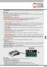
The EB 80 POWERLINK electrical connection comes with two POWERLINK communication ports that can be used to create linear networks.
The network can be divided into several segments, using additional switches.
Make sure that the devices used comply with Industrial Ethernet specifications and support all POWERLINK functions.
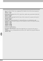
I max [A] = (No. of simultaneously-controlled solenoid pilots x 3.2) + (no. of active solenoid pilots x 0.3)
VDC
Example:
No. of simultaneously-controlled solenoid pilots = 10
No. of active solenoid pilots = 15
VDC = Supply voltage 24
I max = (10 x 3.2) + (15 x 0.3) = 1.5 A
24
Summary of Contents for EB 80 ETHERNET POWERLINK
Page 1: ...MANUALE D USO USER MANUAL ...

