79
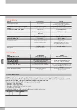
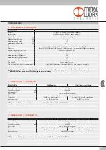
11. TECHNICAL DATA
TECHNICAL DATA
Fieldbus
100 Mbit/S - Half-duplex - Supports auto-negotiation
Factory settings
module denomination: EB80series address number 2
Addressing
Hardware by rotary switch
Supply voltage range
VDC
12 -10% 24 +30%
Minimum operating voltage
VDC
10.8
*
Maximum operating voltage
VDC
31.2
Maximum admissible voltage
VDC
32
***
Protection
Module protected from overload and polarity inversion. Outputs protected from overloads and short-circuits.
Connections
Fieldbus: 2 M12 Female, D encoding, internal switch. Power supply: M8, 4-PIN
Diagnostics
Ethernet POWERLINK: via local LED lights and software messages. Outputs: via local LED lights and state bytes
Bus power supply current absorption
nominal Icc 180 mA at 24 VDC
Maximum number of pilots
128
Maximum number of digital inputs
128
Maximum number of digital outputs
128
Maximum number of analogue inputs
16
Maximum number of analogue outputs
16
Maximum number of inputs for temperatures
16
Data bit value
0 = non-active; 1= active
State of outputs in the absence of communication
Configurable for each output: non-active, holding of the state, setting of a preset state
*
Minimum voltage 10.8VDC required at solenoid pilots. Check the minimum voltage at the power supply output using the calculations shown on page 31.
***
IMPORTANT! Voltage greater than 32VDC will damage the system irreparably.
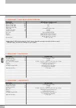
11.3 SIGNAL MODULES - S - DIGITAL OUTPUTS
TECHNICAL DATA
8 M8 Digital Outputs
16 Digital Input terminal board
Output voltage
Corresponding to power voltage
Current for each connector
mA
max 500
Current for each module
mA
max 3000
Type of output
Software-configurable PNP/NPN
Protection
Overload and short-circuit protected inputs
Overload and short-circuit protected outputs
Connections
8 M8 3-pole female connectors
4 connectors 12 pins with spring clamping
Input active signals
One LED for each output
NB
: Digital terminal block outputs are available from software version 1.2 and file XDD Powerlink I4.0 (000002EE_EB80)
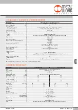
11.2 SIGNAL MODULES - S - DIGITAL INPUTS
TECHNICAL DATA
8 M8 Digital Inputs
16 Digital Inputs terminal board
Sensor supply voltage
Corresponding to power voltage
Current for each connector
mA
max 200
Current for each module
mA
max 500
Input impedance
kΩ
3.9
Type of input
Software-configurable PNP/NPN
Protection
Overload and short-circuit protected inputs
Connections
8 M8 3-pole female connectors
4 connectors 12 pins with spring clamping
Input active signals
One LED for each input
One LED for each output
NB
: Digital terminal block inputs are available from software version 1.2 and file XDD Powerlink I4.0 (000002EE_EB80)
11.1 POWERLINK ELECTRICAL CONNECTION
Summary of Contents for EB 80 ETHERNET POWERLINK
Page 1: ...MANUALE D USO USER MANUAL ...


