background image

14    Conventional Products—DH400 Conventional Air Duct Smoke Detector

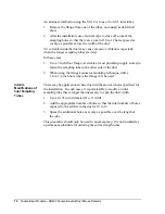
An alternate method to using the ST-10 is to use two ST-5 inlet tubes:

1.

Remove the flange from one of the tubes, and install as described
above.

2.

After the installation, use electrical tape to close off some of the
sampling holes so that there are a total of 10 to 12 holes spaced as
evenly as possible across the width of the duct.

Air currents inside the duct may cause excessive vibration, especially
when the longer sampling tubes are used.

In these cases:

1.

Use a 3 inch floor flange (available at most plumbing supply stores) to
fasten the sampling tube to the other side of the duct.

2.

When using the flange/connector mounting technique, drill a
1 to 1-1/4 inch hole where the flange will be used.

There may be applications where duct widths are not what is specified for
the installation.  In such cases, it is permissible to modify an inlet
sampling tube that is longer than necessary to span the duct width.

1.

Use a 0.193 inch diameter (No. 11) drill.

2.

Add the appropriate number of holes so that the total number of holes
exposed to the airflow in the duct is 10 to 12.

3.

Space the additional holes as evenly as possible over the length of
the tube.

This procedure should only be used in an emergency; it is not intended as
a permanent substitute for ordering the correct length tubes.

Interim
Modifications of
Inlet Sampling
Tubes

Summary of Contents for DH400

Page 1: ...allation Procedures 9 General Information 9 Installation 9 Mounting 10 Wiring Installation Guidelines 15 Perform Detector Check 18 Testing and Maintenance Procedures 19 Testing Duct Detectors 19 Testing Smoke Entry 19 Testing Standby Alarm and Sensitivity 21 Testing Alarms 21 Testing Sensitivity 23 Maintenance 24 Reinstallation 26 Detector Test Log 27 Sample of Test Log 27 Limitations 28 DH400 Con...

Page 2: ...2 Conventional Products DH400 Conventional Air Duct Smoke Detector ...

Page 3: ...r Guide for Proper Use of System Smoke Detectors Technical Bulletin in the Fire Initiating Devices and Notification Appliances Devices Technical Manual FAN 408 which provides detailed information on detector spacing placement zoning wiring and special applications or for non United States installations applicable codes and standards specific to country and locality of installation Failure to follo...

Page 4: ...he management of toxic smoke and fire gases throughout the areas served by the duct system DH400 detectors are designed to operate with 12 or 24 Volts Direct Current VDC UL Listed compatible 2 wire control panels The alarm current must be limited to 100 mA or less by the control panel Auxiliary relay contacts for control purposes are not available for use with the DH400 Control must initiate from ...

Page 5: ...he inlet sampling tube must be ordered separately It must be the correct length for the width of the duct where it will be installed To determine the inlet tube required for different duct widths read Table 4 Sampling Inlet Tubes Required for Different Duct Widths in the Mounting Install the Sampling Inlet Tube section of this technical bulletin Foam Gasket Detector Base Exhaust Filter Adapter Con...

Page 6: ...crews will withstand 10 in lb of tightening torque without damage Accessories M02 04 00 Replacement Test Magnet RA400Z Remote Annunciator Alarm LED RTS451 Remote Test Station Test Switch with Alarm and Power LEDs CRT400 Detector Head Cover Removal Tool Ion only F36 05 00 Replacement Air Filter two per package MOD400R Sensitivity Test Module P48 21 00 Replacement End Plug for Inlet Sampling Tube R5...

Page 7: ...eak to Peak Startup Capacitance 0 02 µF Maximum Standby Ratings 8 5 VDC Minimum 35 VDC Maximum 120 µA Maximum Alarm Ratings 4 2 VDC Minimum at 10 mA 6 6 VDC Maximum at 100 mA Alarm current must be limited to 100 mA or less by the control panel If used the RA400Z remote lamp operates within the specified alarm currents Reset Voltage 2 50 VDC Minimum Reset Time 0 3 sec Maximum Startup Time 34 0 sec ...

Page 8: ...8 Conventional Products DH400 Conventional Air Duct Smoke Detector ...

Page 9: ...herefore it should not be installed above the building roof line and must be protected from the elements 1 Verify duct airflow direction and velocity 2 Drill the mounting holes 3 Secure the detector housing to the duct 4 Install the sampling inlet tube 5 Complete the field wiring 6 Install the filters and check the pressure differential 7 Perform the detector check 8 Install the cover Model DH400 ...

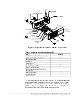
Page 10: ...s over the two small holes Hole A next to the sampling tube bushing holes Hole B previously drilled in the duct Figure 2 dhfig2 Hole A Hole B Duct Wall Speed Nut Figure 2 Speed Nut Mounting Location 1 Remove the duct housing cover 2 Slide the foam gaskets over the tube bushings Figure 3 3 Make sure the two small holes in the gaskets line up with the two base mounting holes 4 Put one 5 16 inch O ri...

Page 11: ...the duct The inlet tube is always installed in the centermost housing bushing with the air inlet holes facing into the airflow The tube is inserted throught the detector housing and into the duct until the tube s mounting flange makes contact with the housing See Figures 3 and 8 for two views of the orientation of the sampling tube in the housing To assist proper installation The tube s mounting f...

Page 12: ...etector Housing Inlet Tube Exhaust Tube Inlet Tube Exhaust Tube Figure 5 Tube Mounting Configurations with Varying Airflow Direction 1 If the tube is longer than the width of the air duct Drill a 3 4 inch hole in the duct directly opposite the hole already cut for the inlet tube 2 If the tube is shorter than the width of the air duct Install the end plug into the inlet tube Figure 5 Sampling tubes...

Page 13: ...ucts wider than eight feet is accomplished by using the ST 10 inlet sampling tube If the tube is shorter than the width of the air duct install the end plug into the inlet tube and support the end opposite the duct detector Figure 5 To install the inlet tube 1 Drill a 3 4 inch hole in the duct directly opposite the hole already drilled for the inlet tube 2 Slide the inlet tube with the flange into...

Page 14: ...o fasten the sampling tube to the other side of the duct 2 When using the flange connector mounting technique drill a 1 to 1 1 4 inch hole where the flange will be used There may be applications where duct widths are not what is specified for the installation In such cases it is permissible to modify an inlet sampling tube that is longer than necessary to span the duct width 1 Use a 0 193 inch dia...

Page 15: ...last foot of conduit should be flexible steel conduit available in electrical supply houses which facilitates easier installation and puts less strain on the conduit holes in the housing Solid conduit connections may be used if desired Smoke detectors and alarm system control panels have specifications for maximum allowable IDC resistance and supervision current Consult the control panel manufactu...

Page 16: ... zone wiring of the detector base should be checked before the detector heads are installed in them To make this possible this base contains a special spring type shorting jumper After a detector base is properly wired and mounted on an electrical box make sure that the jumper is in contact with the base of Terminal 3 This temporary connection shorts the negative in and negative out leads and perm...

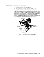
Page 17: ... dust and dirt accumulated Visually inspect the filters at least quarterly Inspect them more often if the dust accumulation warrants it as described in the Testing and Maintenance Procedure section of this technical bulletin The exhaust tube intake tube filter P N F36 05 00 is an example of a replacement filter that can be ordered from System Sensor Foam Gasket Detector Base Exhaust Filter Adapter...

Page 18: ...technical bulletin 4 Perform the Smoke Response Test as described in the Testing Smoke Entry section of this technical bulletin 5 Perform the MOD400 or MOD400R Test and R59 18 00 Calibrated Test Card Tests as described in the Testing Sensitivity section of this technical bulletin 6 Record all test results in the Detector Test Log section of this technical bulletin 1 Install the cover using the fou...

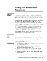
Page 19: ...reafter Testing methods must satisfy the authority having jurisdiction Detectors offer maximum performance when they are tested and maintained in compliance with NFPA 72 National Fire Alarm Code After conducting these tests record the appropriate information in the Sample of Test Log section of this technical bulletin To verify sufficient sampling of ducted air use a manometer to measure the diffe...

Page 20: ...ke Detector Duct Housing dhfig7a Test Magnet Painted Side Toward Housing Detector Head Test Locator Figure 9 Testing Detector Alarm Twist Counterclockwise to Remove Detector Head Twist Clockwise to Install Duct Housing dhfig8a Figure 10 Detector Head Removal ...

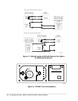
Page 21: ...sories such as the RA400Z and RTS451 3 Verify system control panel alarm status and control panel execution of all intended auxiliary functions such as the fan shutdown damper control 4 Reset the detector by the system control panel The RTS451 remote test station facilitates test of the alarm capability of the duct detector as indicated in the RTS451 Remote Test Station Technical Bulletin in the I...

Page 22: ... agnet Test Switch 7 4 AUX power located at the test station 8 6 4 3 5 4 2 1 24 VAC 10 15 Full wave rectified unfiltered unregulated power m ay be used 24 VDC AUX Power Supplied by User 100 m A Supply Alarm LED Red RTS451 Optional Rem ote Test Station 2 8 VDC in Alarm DH400 Duct Detector M agnet Test Switch 7 AUX power located at the duct detector Figure 11 Wiring Diagram for RTS451 Remote Test St...

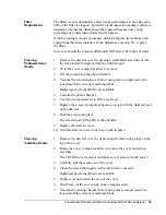
Page 23: ... Remove the photo head cover by placing a small blade screwdriver in the side slot of the detector cover 4 Twist it slightly until the cover can be turned counterclockwise 5 Carefully reinsert the detector head into the duct housing and wait 50 seconds for power up Do not hold the swirl chamber to twist the detector head 6 Insert the no alarm end of the test card into the test slot Figure 12 7 Sli...

Page 24: ... or system undergoing maintenance to prevent unwanted alarms and possible dispatch of the fire department Upon completion of maintenance and any subsequent testing enable any system functions previously disabled for maintenance and notify the authorities that the system is back in service 1 Turn off power to the system 2 Remove and inspect sampling tube filters 3 If filters are heavily coated with...

Page 25: ...osen and blow out any remaining debris Replacement screens RS24 are available 5 Vacuum the photo chamber 6 Use clean compressed air to blow area clean 7 Replace the screen by aligning the arrow on top with the field test port on the detector 8 Push the screen into place The screen should fit tightly to the chamber 9 Replace the detector cover 10 Turn the detector cover clockwise to lock in place 1...

Page 26: ...ver for Cleaning Removable Screen P N RS14 Lock Prong Sensing Chamber Figure 14 Exploded View of the Ion Head 1 Reinstall detector in housing 2 Restore system power 3 Perform a detector check as described in the Perform Detector Check section of this technical bulletin 4 Notify the proper authorities that maintenance has been completed and the smoke detector system is operating again Reinstallatio...

Page 27: ...on Information Manufacturer and Detector Model Serial Number Date Installed Type and Model Number of Detector Head Description of Detector Location Table 6 Test Results and Maintenance Data Date Tested Test Description Test Results Maintenance Performed Comments Detector Test Log Sample of Test Log ...

Page 28: ...ontrols supports this position and strongly recommends that the user read NFPA Standards 90A Installation of Air Conditioning and Ventilation Systems Standard 72 National Fire Alarm Code and 101 Life Safety Code or equivalent codes and standards specific to the country of installation The DH400 air duct smoke detectors are listed per UL 268A Limitations Controls Group FAN 408 507 E Michigan Street...

Reviews: