Conventional Products—DH400 Conventional Air Duct Smoke Detector 21
1.
Look for the presence of the flashing red LEDs through the
transparent housing cover.
2.
The LEDs should flash approximately every ten seconds.
Note: This standby test does not not indicate the detector is in alarm,
rather, that the detector is properly wired, receiving power and
is ready to transmit an alarm.
1.
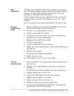
Remove the detector head from the duct housing.
2.
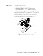
The detector head is removed by turning it counterclockwise about
10 degrees (Figure 11).
3.
The system control panel should indicate a trouble condition.
4.
Replacing the detector head should clear the trouble indication.
1.
Place the painted surface of the magnet into the test locator molded
into the side of the housing (Figure 9).
2.
Verify the red alarm LEDs on the detector latch on, as should any
accessories such as the RA400Z and RTS451.
3.
Verify system control panel alarm status and control panel execution
of all intended auxiliary functions such as the fan shutdown damper
control.
4.
Reset the detector by the system control panel.
The RTS451 remote test station facilitates test of the alarm capability of
the duct detector as indicated in the RTS451 Remote Test Station Technical
Bulletin in the Intelligent Products section of this manual.
Note: The DH400 duct detector must be reset by the system control panel.
To install the RTS451:
1.
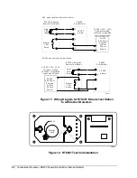
Connect the device (Figure 10).
2.
Wire runs must be limited to 25 ohms or less per interconnecting wire.
3.
Place the test coil in the detector housing with the arrow facing up and
pointing toward the detector (Figure 11).
4.
Attach the test coil leads to the housing terminals as shown.
Polarity is not important.
5.
Firmly screw the bracket in place over the test coil.
Testing
Standby, Alarm,
and Sensitivity
Standby Test
Trouble Test
Testing Alarms
M02-04-00
Magnet Test
RTS451 Remote
Test Station


