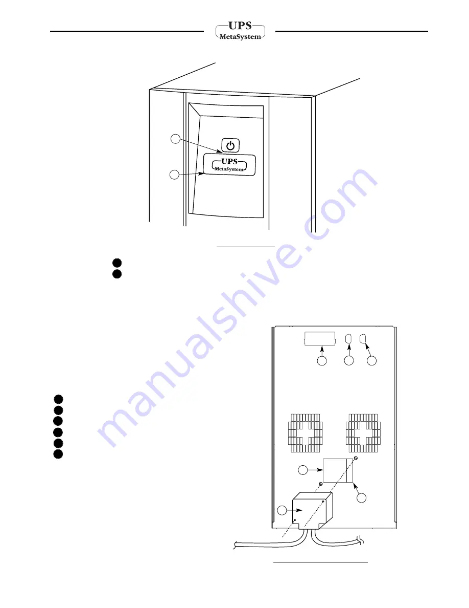
BUTTON TO SWITCH ON / SWITCH OFF
MULTICOLOUR OPERATING STATUS INDICATOR LIGHT (GREEN / YELLOW / RED)
Single Cabinet
(fig. 2)
:
3
Input/Output connector
4
Input/Output plug
5
Input fuse
6
RS232 serial interface outlet (9-pin female)
7
Logic signals outlet (9-pin male)
8
SNMP Interface
2
1
2
1
8
4
7
6
5
24
Electrical connections
3 - Installation
Front panel
Installation procedure
Fig. 3 Electrical Connections
Fig. 2 Front Panel
To the loads
To the mains
electricity supply
3


