46
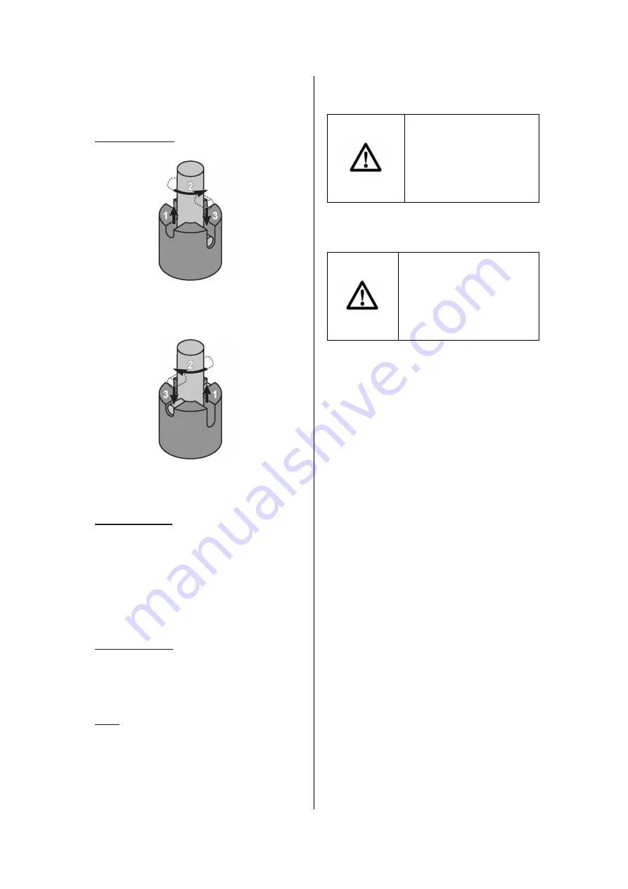
Spindle Lock Head Lock_down
Description of Selected Functions
Head Lock-down:
Align pin with deep groove to lock cutting
head.
Align pin with shallow groove to unlock
cutting head.
Guard operation:
When the Handle is lowered, the Lower Guard
raises automatically. When the Handle is
raised the Lower Guard returns to its safety
position. Keep hands clear of the Blade when
the Handle is lowered. Do not interfere with
the proper movement of the Lower Guard.
Slide Lock Knob:
Tighten this to prevent the cutting head from
sliding back and forth for chopping cuts.
Loosen this to allow the cutting head to slide.
Note: Additional functions are explained
elsewhere in the manual.
INSTRUCTIONS FOR USE
Read the ENTIRE
IMPORTANT SAFETY
INFORMATION section at
the beginning of this
manual including all text
under subheadings therein
before set up or use of this
product.
TOOL SET UP
TO PREVENT SERIOUS
INJURY FROM
ACCIDENTAL
OPERATION:
Turn the Power Switch of the
tool off and unplug the tool
from its electrical outlet before
performing any procedure in
this section.
TO PREVENT SERIOUS INJURY: DO NOT
OPERATE WITH ANY GUARD DISABLED,
DAMAGED, OR REMOVED. Moving guards
must move freely and close instantly.
Using the Workpiece Extension Supports
1. The Table Extensions are inserted into
each side of the Table, and locked in place
using the Wing Screws.
2. When properly installed, the upper face of
the Table
Extensions are level with the
Table, and provide a wider support surface
for the workpiece.
3. Support the workpiece to be level with the
table, and so that after the cut is made the
cut off pieces will not fall. Use sawhorses
or other supports (not included) to support
longer workpieces.
4. If the workpiece is not level, you will make
an unintentional bevel cut in the material.
If the workpiece is not supported, it will bind
the blade and may cause the material to
kick back, potentially causing injury.


