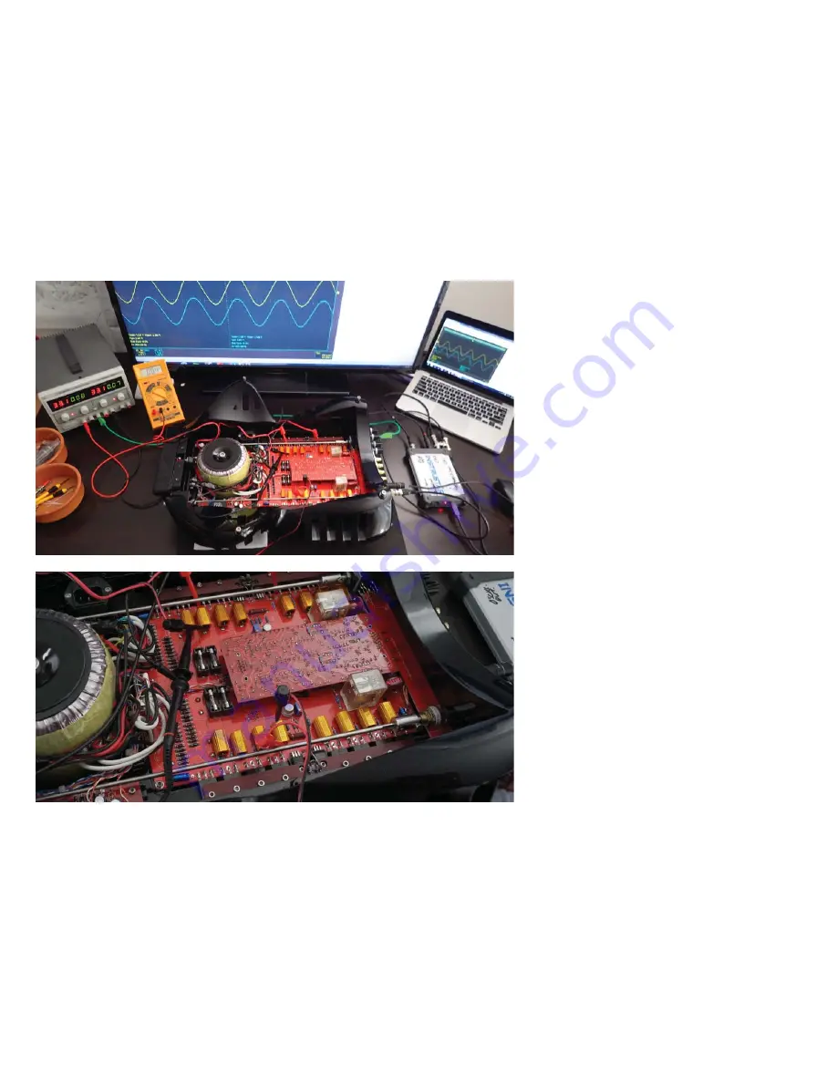
TESTING
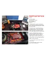
TOOLS REQUIRED:
Dual Channel Oscilloscope
Signal Generator
30V x 2 Power Supply
Multimeter
1. Flip the ampli
fi
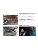
er to reveal the underside and
remove the bottom panel [M3 alun bolts]. Remove
the VU Module. Rotate the biasing trimpots VR5 &
VR5a fully clockwise.
2. Connect the + and - and GND supply lines at
the FUSEHOLDERS or CENTER PIN OF POWER
TRANSISTORS [+ 2987, - 1227] to the external
current limiting Power Supply with m/-
35VDC output voltage and 100 mA current limiting
3. Generate a 1.0kHz frequency sine wave.
Connect your oscillator to any of the inputs 1,2,3
and select it with the rotary switch. Adjust the
VOLUME control to position 9. Connect the
Speaker outputs to your Oscilloscope’s channel 2.
4. Install or replace the 4 fuses with MA205 [FAST
BLOW] 1.0 A [for extra safety)
5. Power the module on and check that there is no
current limiting.
You should now be able to see the ampli
fi
er
output on the Oscilloscope ch2.
maintenance
Summary of Contents for solitaire
Page 1: ...metaxas sins solitaire depuis 1981 ...
Page 3: ...solitaire metallic automotive paint option ...
Page 5: ......
Page 7: ......
Page 9: ......
Page 11: ......
Page 14: ...future proof modular construction the heart of the solitaire two updateable modules ...
Page 16: ......
Page 18: ...integrated or stereo version ...
Page 20: ......
Page 21: ...history 4 decades of design 1980 s in Brunswick Street North Fitzroy ...
Page 22: ......
Page 24: ......
Page 25: ...our master tapes ...
Page 26: ......
Page 31: ......
Page 33: ......
Page 37: ...solitaire anodised option any color you like ...
Page 38: ......
Page 43: ......


