background image

f.

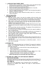
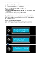
USER SELECTABLE POWER GRAPH

1.

With  the system in  the  Ready  or Power  Modes,  press  and  hold  the  Output
Selector/Command Button for 3 seconds until the time flashes

2.

Release the Output Selector/Command Button.

3.

Press and hold the Output Selector/Command button for 3 seconds.

4.

Release the Output Selector/Command Button.

5.

Press  the  Output  Selector/Command  Button  until  the  desired  bar  graph  is
displayed; Standard or UltraFine.

6.

Press  and  hold  the  Output  Selector/Command  button  for  3  seconds  to
return to operation.

7.

APPLICATION NOTES:

a.

EXTENDING TIP LIFE

1.

Each  day,  remove,  inspect,  and  clean  the  cartridge  shaft  and  handle  using
denatured alcohol and a clean cloth. Stubborn flux deposits on the shaft (and
on the entire SMTC, PTTC & TATC tip) can be removed using a brass brush.

2.

After  you  turn  on  the  system,  and  each  time  you  return  the  tip to  the  holder,
apply solder to the tinned surfaces of the tip. The solder protects the tip from
oxidation and prolongs the life of the tip.

3.

Select  the  lowest  temperature  series  tip  cartridge  that  will  do  the  job.  Lower
temperatures decrease tip oxidation and are easier on the components being
joined.

4.

Use  fine  point  tips  only  when  necessary.  The  plating  on  fine  precision  tips  is
less durable than the plating on larger tips.

5.

Do  not  use  the  tip  as  a  prying  tool.  Bending  the  tip  can  cause  the  plating  to
crack, shortening tip life.

6.

Use  the  minimum  activation  flux,  appropriate  to  solder  type,  as  necessary  to
do the job. Higher activation flux is more corrosive to the tip plating.

7.

When  making  a  solder  connection,  apply  fresh  solder  to  the  items  being
joined, 

not

 to the hot soldering tip.

8.

Switch the system off when not in use.

9.

Do not apply pressure to the tip. More pressure does not equal more heat. To
improve heat transfer, use solder to form a thermal bridge between the tip and
the solder joint.

10. Clean  the  tip  on  a  clean,  damp  sponge  or  a  coiled  brass  cleaner  --  not  on  a

rag or dirty, dry sponge.

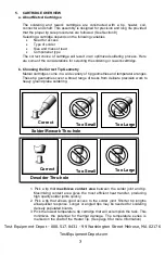
b. DETINNED TIPS

If a tip is not wetting with solder then it is detinned. This exposes the plating to 
oxidation  and  substantially  degrades  the  heat  transfer  efficiency  of  the  tip. 
Detinning is caused by:  

Failure to keep the tip covered with fresh solder during idling periods.

High tip temperatures.

Lack of sufficient flux in soldering operations.

Wiping  the  tip  on  dirty  or  dry  sponges  and  rags.  (Always  use  a  clean,
damp, industrial grade, sulfur-free sponge or brass sponge)

Impurities in the solder or on the surfaces to be soldered.

NOTE: Detinned tips are preventable with proper daily care! 

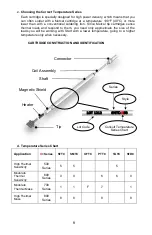
c. CHOOSING THE CORRECT TIP CARTRIDGE AND GEOMETRY

MULTI-LEAD PACKAGES 

Multi-lead components can be drag soldered using Metcal hoof-tip cartridges. Tin 
the working face of the tip with solder and gently drag it across the array of leads. 

SMT REMOVAL 

First,  measure  the  dimensions  of  your  component,  then,  use  the  SMTC 
charts 

that  are  available  from  Metcal’s  web  page  to  match component 

and tip dimension. 

Summary of Contents for MX-500S

Page 1: ... 6ROGHULQJ HVROGHULQJ DQG 5HZRUN 6 VWHP 8VHU XLGH Test Equipment Depot 800 517 8431 99 Washington Street Melrose MA 02176 TestEquipmentDepot com ...

Page 2: ... LIH E HWLQQHG 7LSV 6 7528 6 227 1 8 6 7 DUUDQW 2 QWHUQDWLRQDO ZDUUDQWV WKH 0 6 VWHP DJDLQVW DQ GHIHFWV LQ PDWHULDOV RU ZRUNPDQVKLS IRU IRXU HDUV IURP WKH GDWH RI SXUFKDVH E WKH RULJLQDO RZQHU 7KLV DUUDQW H FOXGHV QRUPDO PDLQWHQDQFH DQG VKDOO QRW DSSO WR DQ RSHQHG PLVXVHG DEXVHG DOWHUHG RU GDPDJHG LWHPV I WKH SURGXFW VKRXOG EHFRPH GHIHFWLYH ZLWKLQ WKH ZDUUDQW SHULRG 2 QWHUQDWLRQDO ZLOO UHSDLU RU U...

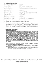
Page 3: ...ipped with a self regulating heater which senses its own temperature and closely maintains its pre set idle temperature for the life of the heater tip all controlled by OK International s proprietary SmartHeat Technology The tip temperature is determined by the inherent metallurgical properties of the heater no external adjustment or equipment is required This eliminates spikes and transients asso...

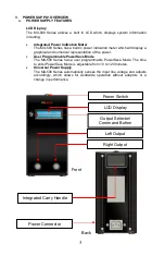
Page 4: ...on of the power User Programmable PowerSave Mode The MX 500 Series has a user programmable PowerSave Mode The time to enter PowerSave Mode is adjustable from 10 to 120 minutes Universal Power Supply The MX 500 Series automatically senses the input line voltage and adjusts accordingly which allows for worldwide operation without adaptors or a change in performance Front LCD Display Output Selector ...

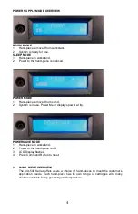
Page 5: ... stand 2 System is in use Power Meter displays power at tip POWERSAVE MODE 1 Hand piece in workstand 2 Power to the hand piece is off 3 LCD Display flashes 4 Press Command Button to reset 4 HAND PIECE OVERVIEW The MX 500 Series offers users a choice of hand pieces to meet the customer s application needs Each hand piece has its own range of cartridges with many choices available for tip geometry a...

Page 6: ...These tip geometries cover a broad range of tasks from delicate precision work to heavy ground plane soldering 1 Pick a tip that maximizes contact area between the solder joint and tip Maximizing contact area gives the most efficient heat transfer producing high quality solder joints quickly 2 Pick a tip that allows good access to the solder joint Shorter tip lengths allowquicker response Longer o...

Page 7: ...e size of the loads you will be working with Start with a lower temperature going to a higher temperature only when necessary d Temperature Series Chart Application X Series STTC SMTC UFTC PTTC TATC STDC High Thermal Sensitivity 500 Series 5 5 5 Moderate Thermal Sensitivity 600 Series 0 0 6 6 0 Moderate Thermal Mass 700 Series 1 1 F 7 1 High Thermal Mass 800 Series 8 8 8 8 Connector Coil Assembly ...

Page 8: ...IP CARTRIDGES 1 Make sure the system is turned off 2 Pull out the cartridge using the Cartridge Removal Pad MX CP1 NOTE THE TIP CARTRIDGE MAY BE HOT DO NOT USE METAL TOOLS PLIERS ETC TO REMOVE CARTRIDGES 3 Push a new cartridge into the handle 4 Place hand piece s into associated work stand s 5 Push the power switch ON The new cartridge will heat up to temperature quickly c MX PTZ AND TALON OPERATI...

Page 9: ...g tip life 6 Use the minimum activation flux appropriate to solder type as necessary to do the job Higher activation flux is more corrosive to the tip plating 7 When making a solder connection apply fresh solder to the items being joined not to the hot soldering tip 8 Switch the system off when not in use 9 Do not apply pressure to the tip More pressure does not equal more heat To improve heat tra...

Page 10: ...lem Low power operation of the unit Check input power to the unit The unit can draw up to 10A of current at 110V Do not plug into power sources such as power strips that are rated less than 10A Multiple high current devices plugged into the same electrical circuit can cause low power operation distribute high current devices among multiple circuits or increase the electrical circuit capacity Probl...

Page 11: ...ded for use by persons including children with reduced physical sensory or mental capabilities or lack of experience and knowledge unless they have been given supervision or instruction concerning use of the appliance by a person responsible for their safety Children should be supervised to ensure that they do not play with the appliance Although the systems offer superior EOS Electrical Overstres...

Reviews:

Related manuals for MX-500S