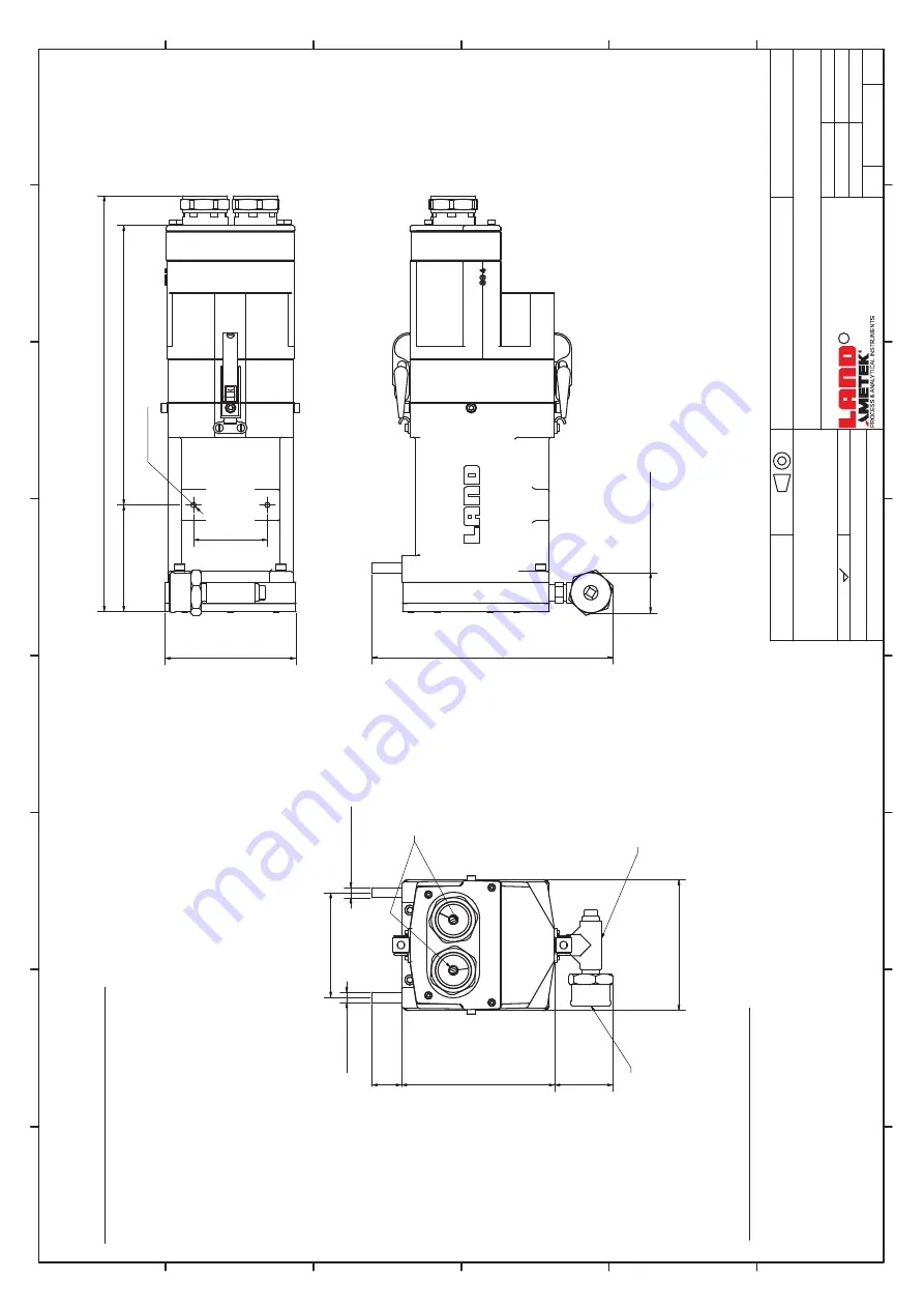
background image

1

1

2

2

3

3

4

4

5

5

6

6

7

7

8

8

A

A

B

B

C

C

D

D

E

E

F

F

TH

IS

 D

RA

W

IN

MU

ST

 N

OT

 B

E C

OP

IE

OR

 U

SE

OT

HE

TH

AN

 FO

TH

E P

UR

PO

SE

 O

W

HI

CH

 IT

 W

AS

 IS

SU

ED

 W

IT

HO

UT

 T

HE

 W

RI

TT

EN

 PE

RM

IS

SI

ON

 O

F:-

DR

G.

 T

IT

LE


MA

TE

RI

AL

FI

NI

SH

Cr

ea

ted

 by

Ap

pr

ov

ed

 by

DA

TE

DR

G.

No

.

SU

RF

AC

FI

NI

SH

AL

L S

HA

RP

 C

OR

NE

RS

 R

EM

OV

ED

Te

ch

nic

al 

ref

er

en

ce

SC

AL

E

LA

ND

 IN

ST

RU

ME

NT

S I

NT

ER

NA

TI

ON

AL

 LT

D,

 D

RO

NF

IE

LD

, S

18

 1D

J

C

SH

EE

T

OR

IG

IN

AL

LY

 U

SE

ON

 PR

OD

UC

TY

PE

Re

vis

ion

S.L

on

sd

ale


81

51

20

1

08

/1

0/

20

21

In

sta

lla

tio

n D

raw

ing

s f

or

 LM

IR

-M

W

IR

 64

0 I

ma

ge

r S

ys

tem

03

10

 LW

IR

 64

0 C

am

era

\A

cc

es

so

rie

s


L

20

21


De

sig

n E

ng

ine

er

ing

PR

OJ

EC

TI

ON

DR

G.

Siz

e

St

an

da

rd

 A

ss

em

bl

y

DO

CU

ME

NT

 T

YP

E

A2

No

t t

Sc

al

e

of

 1

Al

l M

at

er

ia

ls 

an

Fi

ni

sh

es

 to

 b

Ro

HS

 C

om

pl

ia

nt

 to

 D

ire

ct

iv

20

11

/6

5/

EU

 &

 (E

U)

 2

01

/ 8

63

C

he

m

ic

al

in

 b

re

ac

of

 E

U

 R

E

A

C

H

 o

r U

S

 T

S

C

A

 li

m

its

 in

 th

is

 p

ro

du

ct

 m

us

t b

re

po

rte

to

 L

an

In

st

ru

m

en

ts

CO

NF

O

RM

TO

 B

88

88

TO

LE

RA

NC

IN

IS

O

 8

01

5

IS

O

 2

76

-

RE

SP

ON

SI

BL

DE

PT

D.

Br

am

ha

ll

70 

[2,

8]

10

[4

,0

]

26

[1

0,

4]

124

 [4

,9]

39

[1

5,

5]

M

6x

- 6

H

Ø

9,

[3

/8

"]

Ø9

,5

 [3

/8

"]

99

 [3

,9

]

145

 [5

,7]

28 

[1,

1]

12

[4

,9

]

Re

qu

ir

ed

 W

at

er

 S

up

pl

Co

nd

iti

on

s:

  •

W

at

er

 s

up

pl

m

us

t b

cle

an

 fi

lte

re

w

at

er

 w

ith

 a

 p

le

ve

l b

et

w

ee

6.

an

8.

5

Ra

te

 o

f W

at

er

 H

ar

dn

es

=

 <

15

0m

g/

l C

al

ciu

m

 C

ar

bo

na

te

W

at

er

 c

oo

le

d:

 F

lo

w

 <

 1

 l/

m

in

 / 

13

Ga

l/h

r)

Ai

r c

oo

le

d:

 F

lo

w

 <

 4

50

l/m

in

 / 

16

cf

m

M

ax

im

um

 w

or

ki

ng

 p

re

ss

ur

e:

 7

00

kN

/m

² 

/ 7

 B

ar

 (1

00

ps

i)

Pl

ai

pi

pe

 c

on

ne

ct

io

ns

 3

/8

in

 /9

.5

m

m

 d

ia

.

M

AX

 In

le

t W

at

er

 te

m

pe

ra

tu

re

 =

 4

C

R

eq

ui

re

Ai

Su

pp

ly

 C

on

di

tio

ns

:

  •

Ai

r s

up

pl

m

us

t b

cle

an

 fi

lte

re

an

re

gu

la

te

in

st

ru

m

en

t a

ir.

M

IN

 F

lo

w

 R

at

e=

 3

50

 l/

m

 fo

r u

se

 in

 a

pp

lic

at

io

ns

 u

to

 1

00

C

M

IN

 P

re

ss

ur

=

 1

.4

 b

ar

 fo

r u

se

 in

 a

pp

lic

at

io

ns

 u

to

 1

00

M

AX

 O

ut

le

t A

ir 

te

m

pe

ra

tu

re

 =

 4

C


38

 [1

,5

]

Ø

Ai

r I

nl

et

 fo

r P

ur

ge

Le

av

En

ou

gh

 S

pa

ce


Be

lo

w

To

 A

llo

w

 F

or


Ai

r P

ur

ge

 F

ee

Pi

pe

W

at

er

 C

oo

lin

IN

/O

UT

of

f M

32

 C

ab

le

 G

la

nd

s

228

 [9

,0]

55 

[2,

2]

Summary of Contents for LAND LWIR

Page 1: ...g Wavelength Infrared Thermal Imaging Camera i Q U A L I T Y C U S T O M E R S O L U T I O N S LWIR THERMAL IMAGER INSTALLATION GUIDE PUBLICATION NO 814975 LANGUAGE ENGLISH ISSUE 1 DATE 07 DECEMBER 20...

Page 2: ...sensitive devices Equipment Operation Use of this instrument in a manner not specified by AMETEK Land may be hazardous Read and understand the user documentation supplied before installing and operat...

Page 3: ...r Repair If you need to return goods for repair please contact our Customer Service Department for details of the correct returns procedure Any item returned to AMETEK Land should be adequately packag...

Page 4: ...agrams 4 0 5 Using the Web Server Interface 5 1 5 1 Connecting to the Web Server 5 1 5 2 About the Web Server Interface 5 3 5 3 About the Web Server Menu 5 4 5 4 Settings 5 4 5 5 Frame Settings 5 5 5...

Page 5: ...oose a mounting location that permits easy access to the system components wherever possible as this will speed up any system maintenance and repair Ensure that the mounting locations chosen for the c...

Page 6: ...cription Options Meaning LWIR Series Name LWIR Long wavelength infrared 640 Pixel Resolution 640 640 x 480 pixels 0 500C Temperature Range 0 500C 0 to 500 C 100 1000C 100 to 1000 C 50 Horizontal Field...

Page 7: ...Compliance EMC EN 61326 1 Camera Supply and I O Digital Connections M12 X coded 8 way connector 10 100 1000 Ethernet IEEE 802 3 at PoE Analog Connections 8 pin Binder Connector 2 pins 12 24V DC Power...

Page 8: ...Green Camera Temperature OK Yellow Flashing Camera Temperature Warning Red Camera Temperature Alarm Thermal Imaging PSU Module UL Approved Components Connections Power supply Gb Ethernet communicatio...

Page 9: ...be powered by an alternative power supply via cable Part N 806032 or Part N 806033 See section 3 2 3 1 Connecting the mains input to the TRACO Power Supply Unit The TRACO Power Supply Unit is supplied...

Page 10: ...ower Supply Unit and disassemble the remaining parts of the connector 5 Slide the rear locking ring gasket and shell body over the mains input cable 6 Strip back the mains cable wires to the appropria...

Page 11: ...n Guide Fig 3 7 8 Attach the mains cable to the Input connector of the Power Supply Unit Fig 3 7 You can now connect the TRACO Power Supply Unit to the LWIR camera via Interface PCB Part N 807941 Refe...

Page 12: ...STALLATION DIAGRAMS 4 Installation Guide 4 0 This section of the Installation Guide provides a series of simple installation diagrams covering the installation of the LWIR thermal camera and its mount...

Page 13: ...o Scale 1 of 17 All Materials and Finishes to be RoHS Compliant to Directive 2011 65 EU EU 2015 863 Chemicals in breach of EU REACH or US TSCA limits in this product must be reported to Land Instrumen...

Page 14: ...sdale 740 123 1 25 08 2021 Installation Drawings for LMIR MWIR 640 Imager System 0310 LWIR 640 Camera Accessories c L 2021 Desiign Engineering PROJECTION DRG Size Standard Assembly DOCUMENT TYPE A2 No...

Page 15: ...EU REACH or US TSCA limits in this product must be reported to Land Instruments CONFORMS TO BS 8888 TOLERANCING ISO 8015 ISO 2768 RESPONSIBLE DEPT D Bramhall 71 2 8 155 6 1 441 17 4 168 6 6 170 6 7 89...

Page 16: ...n to the flange on the purge Ensure the lens is located onto the recess face Fasten securely in place Assembly Instructions for Mounting Camera to Housing 1 Locate the M5 countersink screw to Camera C...

Page 17: ...liant to Directive 2011 65 EU EU 2015 863 Chemicals in breach of EU REACH or US TSCA limits in this product must be reported to Land Instruments CONFORMS TO BS 8888 TOLERANCING ISO 8015 ISO 2768 RESPO...

Page 18: ...mits in this product must be reported to Land Instruments CONFORMS TO BS 8888 TOLERANCING ISO 8015 ISO 2768 RESPONSIBLE DEPT D Bramhall 70 2 8 101 4 0 265 10 4 124 4 9 393 15 5 M6x1 6H 9 5 3 8 9 5 3 8...

Page 19: ...PROJECTION DRG Size Standard Assembly DOCUMENT TYPE A2 Not to Scale 7 of 17 All Materials and Finishes to be RoHS Compliant to Directive 2011 65 EU EU 2015 863 Chemicals in breach of EU REACH or US T...

Page 20: ...nd Finishes to be RoHS Compliant to Directive 2011 65 EU EU 2015 863 Chemicals in breach of EU REACH or US TSCA limits in this product must be reported to Land Instruments CONFORMS TO BS 8888 TOLERANC...

Page 21: ...ess Imager Power Supply AC DC 120W 24VDC Traco Tex Power Supply Refer to Traco Instructions for Mounting and Safety Requirements 4 6 83 164 Customer Supplied 110 230V AC Cable 805755 AMPHENOL C016 20D...

Page 22: ...ess Imager Power Supply AC DC 120W 24VDC Traco Tex Power Supply Refer to Traco Instructions for Mounting and Safety Requirements 4 6 164 83 807942 Din Rail Mounted Interface PCB Customer Supplied 110...

Page 23: ...Std Temp M12 Ethernet X Coded Connector M12 Ethernet X Coded Connector Free Ends Wired in to Din Rail Connect to Internal M12 Socket or to RJ45 with Std Cables 813478 Thermal Imaging PSU Module UL App...

Page 24: ...Ethernet X Coded Connector 813514 10m Imager Power I O Cable High Temperature 815071 25m Imager Power I O Cable High Temperature 814968 50m Imager Power I O Cable High temperature or 807950 5 m Image...

Page 25: ...thernet Cable Entry Connect to Internal M12 Socket M12 Ethernet X Coded Connector 813514 10m Imager Power I O Cable High Temperature 815071 25m Imager Power I O Cable High Temperature 814968 50m Image...

Page 26: ...om Ethernet Switch or Desktop PoE Straight to PC or Laptop 809294 5m M12 to RJ45 Cable Std Temp 814616 20m M12 to RJ45 Cable Std Temp 814617 50m M12 to RJ45 Cable Std Temp High temp M12 M12 variants c...

Page 27: ...N PERMISSION OF DRG TITLE MATERIAL FINISH Created by Approved by DATE DRG No SURFACE FINISH ALL SHARP CORNERS REMOVED Technical reference SCALE LAND INSTRUMENTS INTERNATIONAL LTD DRONFIELD S18 1DJ C S...

Page 28: ...LWIR 640 Camera Accessories c L 2021 Design Engineering PROJECTION DRG Size Standard Assembly DOCUMENT TYPE A2 Not to Scale 16 of 17 All Materials and Finishes to be RoHS Compliant to Directive 2011...

Page 29: ...eb browsers are supported by the LWIR Web Server Google Chrome Microsoft Edge Mozilla Firefox Connection can be made either directly to the Ethernet port on the camera or via an Ethernet switch on the...

Page 30: ...Select the Internet Protocol option and click on Properties 4 Select the Use the following IP address option and enter the values IP address 10 1 10 150 Subnet mask 255 255 0 0 the default IP address...

Page 31: ...lettes available 8 Temperature measurement span user adjustable Upper and lower limits can be set to any points within measurement range of LWIR 9 Full screen ON OFF control 10 Save Camera Settings Al...

Page 32: ...settings For more information see Sections 5 6 and 5 7 I O allows you to set up to three outputs or two outputs and one input For more information see Section 5 8 Information gives read only informati...

Page 33: ...ssivity value where 4mA 0 10 and 20mA 1 00 For more information on Emissivity visit www ametek land com Background Temperature The temperature of the area surrounding an object being measured can have...

Page 34: ...a heated chamber or furnace the temperature of the furnace wall will affect the reading You can use the Background Temperature setting to input this temperature value which will be taken into account...

Page 35: ...ermal image click and drag the mouse pointer to create a rectangle in the location where you want the ROI to be The ROI details are updated to show the co ordinates and size of the ROI 3 To help see t...

Page 36: ...covered by the ROI you can either select a Manual input and type in the required Emissivity value or set it via the slider or you can choose to have the Emissivity set via a 4 to 20mA current input mA...

Page 37: ...a A typical I O interface is shown in Fig 5 3 Fig 5 3 Typical Web I O Interface The interface also shows the pin connections for the outputs inputs on the LWIR cable connector The following outputs in...

Page 38: ...output if it goes outside the range 600 C to 750 C You can specify multiple triggers for the relay by simply clicking on the Add button For a relay output with multiple triggers if the Alarm logic co...

Page 39: ...utput 3 the Relay settings are identical in operation to those of Output 2 The options available for the Command input Cmd In for Input Output 3 each relate to the LWIR Camera and are as follows NUC t...

Page 40: ...e covers the entire temperature range of your LWIR Thermal Imaging Camera either 0 to 500 C or 100 to 1000 C However your application may have temperatures which are well within these lower and upper...

Page 41: ...hermal imaging camera 5 11 2 Averager Refer to Fig 4 2 The Averager time function can be used to smooth the temperature output signal in relation to the temperature input The Averager response can be...

Page 42: ...itching on OFF delay Time period between the temperature falling below the threshold level and the Peak Picker function switching off In Hold mode at the end of the OFF delay the temperature output va...

Page 43: ...ction Refer to Fig 5 6 The Sample and Hold time function is useful especially for measuring intermittent processes e g items on a conveyor belt The presence of a hot object can be used to activate the...

Page 44: ...il PSU Interface PCB and Ethernet Switch 815180 Desktop PoE Power Supply 805024 6 3 Power I O Cables Standard Temperature Cables Camera to DIN Rail PSU Connection PCB Thermal Imaging PSU Description P...

Page 45: ...Part N 25m M12 to M12 communication cable 2 x Connectors Standard temperature 810794 50m M12 to M12 communication cable 2 x Connectors Standard temperature 810889 Camera to RJ45 Ethernet port Thermal...

Page 46: ...Horizontal FOV 11 or 6 deg 813479 Industrial Mounting Splash protection plate Suitable for use with cameras with Horizontal FOV 50 or 28 deg 814876 LWIR 640 light housing with purge Light Housing Pro...

Page 47: ......

Page 48: ...to meet your unique applications Enhancing user skills by providing access to product and application experts AMETEK Land s global service network provides unparalleled after sales services to ensure...

Reviews: