3 - 1
LWIR
Thermal Imaging Camera
Installation Guide
ELECTRICAL
CONNECTIONS
3
The basic system electrical connections are as follows:
•
Mains input to the TRACO Power Supply Unit*
•
24V output from TRACO Power Supply Unit* to the LWIR camera
•
Ethernet cable from LWIR Camera to the Process Imaging Workstation
* The LWIR Camera can be powered by an alternative power supply, via cable
Part Nº 806032 or Part Nº 806033 (See section 3.2).
3.1 Connecting the mains input to the TRACO Power Supply Unit
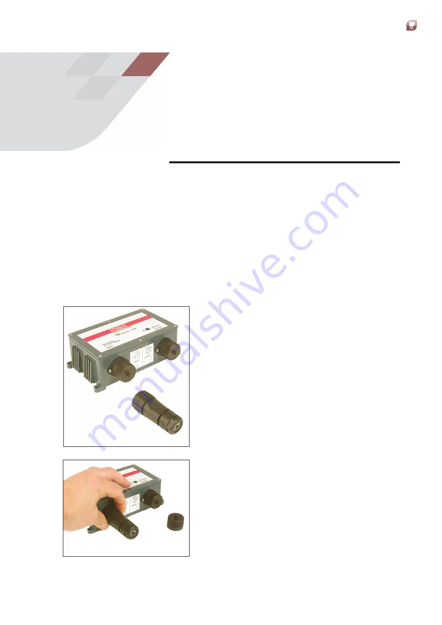
The TRACO Power Supply Unit is supplied with
a 3-pin AC input connector (Fig. 3-1). You will
need to disassemble this connector to install
the cable.
1) Unscrew the cover from the mains
Input
on the Power Supply Unit.
Fig. 3-1
Fig. 3-2
2) The easiest way to disassemble the 3-pin
AC input connector is to first screw the
connector assembly onto the input socket
(Fig. 3-2).
Summary of Contents for LAND LWIR
Page 47: ......


