Installation Manual
MX15 Series
6
1. Introduction
This installation manual is provided in hardcopy format and contains information on the
installation only of MX15 Series power sources with the programmable controller.
All other MX15 Series manuals are provided in Adobe Acrobat PDF format on CD ROM P/N
CIC496. The CD ROM is included in the MX15 Series Ship kit.
1.1 General Description
The MX Series AC and DC power source systems are high efficiency, floor standing AC and DC
power sources that provide a precise output with low distortion. Available voltage ranges are 150
Vac, 300 Vac and 400 Vac in AC mode and 200 Vdc and 400 Vdc in DC mode. All MX15 units
have a single-phase output.
Models with a -1 designation provide full front panel operation but do not include a RS232C or
IEEE-488 remote control interface. An optional RS232C/IEEE-488 control interface can be added
at the time of order however (-P) option. Models with the Pi controller offer several additional
standard features, including the RS232C/IEEE-488 interfaces, arbitrary waveform generation,
and additional measurement functions.
The MX Series units are contained in a compact floor standing enclosure on casters. This allows
the units to be moved around more easily.
Read the installation instructions carefully before attempting to install and operate the MX Series
power systems.
1.2 Manual organization and format
All user documentation for California Instruments power sources is provided on CDROM in
electronic format. (Adobe Portable Document Format) The required Adobe PDF viewer is
supplied on the same CDROM. This Installation manual is provided only in hardcopy form to
ensure that the installation information is available to all MX users and installers.
To request a hardcopy of other MX Series manuals from California Instruments, contact customer
service at
support@calinst.com
. There will be an additional charge for printed manuals. You can
also print these manuals directly from the included CD ROM.
Summary of Contents for MX15
Page 2: ......
Page 3: ......
Page 6: ...ii This page intentionally left blank ...
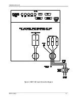
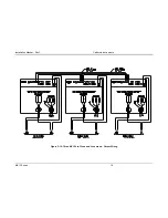
Page 14: ...Installation Manual MX15 Series 10 Figure 2 3 MX15 AC Input Connection Diagram ...


