Installation Manual
MX15 Series
8
2.3 Mechanical Installation
The MX15's are completely self-contained power sources. They are to be used free standing on
a solid surface. The units are fan cooled, drawing air in from the front and exhausting at the rear.
The front and back of each unit must be kept clear of obstruction and
a 6” clearance must be
maintained to the rear. Special consideration of overall air flow characteristics and the resultant
internal heat rise must be considered at all times to avoid self heating and over temperature
problems.
2.4 AC Input Connections and Wiring
Three phase Delta or Y AC input voltage of sufficient amperage (consult AC input specifications
for maximum AC current per phase) is required to power the MX Series.
Note: AC power should be routed through a properly sized and rated three-phase
PROTECTIVE CIRCUIT BREAKER or similar branch circuit protection device with
disconnect capability. This will protect building wiring and other circuits from
possible damage or shutdown in case of a system problem. It will also facilitate
removing AC input power to the MX system in case of service or reconfiguration
requirements.
Note: AC input wiring and connections must conform to local electrical safety codes that
apply. Always consult a qualified electrician prior to installation of any MX System.
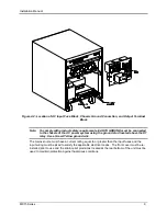
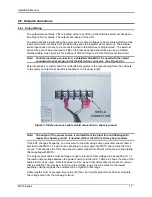
AC input connections are to be made directly to the input fuse block. The input fuse block is
located on the lower right hand corner of the rear of the MX15 chassis. To access the input fuse
connection block, the protective rear cover needs to be removed first.
CAUTION: Always disconnect any input power completely when removing any
protective cover and allow the internal capacitors to fully discharge (minimum
of 15 mins) before removing any cover. See Figure 2-2 for details.
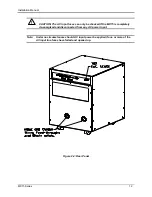
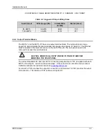
No wiring for AC input connections is provided with the MX Series and must be provided by the
end user or installer. Input wiring should be entered through the right hand side (when facing the
back of the MX15, see Figure 2-4) wire access opening located at the rear bottom of the MX15
chassis.
Summary of Contents for MX15
Page 2: ......
Page 3: ......
Page 6: ...ii This page intentionally left blank ...
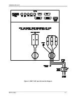
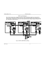
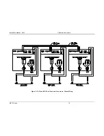
Page 14: ...Installation Manual MX15 Series 10 Figure 2 3 MX15 AC Input Connection Diagram ...


