background image

26

A01-00055 Rev M

5.0 MAINTENANCE

STORAGE


A charged battery, disconnected from a UPM or load, can maintain ideal 

voltage for approximately six months before recharge is necessary. 

A discharged battery needs to be recharged within 72 hours of the 

discharge to avoid permanent battery damage. Storing a UPM with the 

battery connected can cause permanent battery damage and therefore, 

the battery must always be disconnected when storing the UPS.

The UPM may be stored for extended periods in an environment that 

does not subject the UPM to extremes of temperature or humidity.

When storing for extended periods, the battery should be charged every 

six months. If the storage location is characterized by above 77℉

temperature, the battery should be recharged every two months. The 

UPM does not need to be turned on for charging to occur – it only 

needs to be plugged in with batteries connected. Batteries must be 

disconnected when changing cycle is complete and UPM is returned to 

storage. 

NOTE:  

This product is not designed for continuous use on batteries. UPM 

should always be plugged in to AC mains voltage when not being 

used in battery back-up mode to avoid damaging internal batteries, 

resulting in the battery not operating correctly (i.e. overheating or 

inability to retain a charge).

The UPM firmware in this unit provides an additional warning and 

alarm to help prevent and detect this condition. 

1. 

Battery Connected Warning – helps prevent the UPM from being 

stored with the battery connected. This will cause the display to 

flash the pattern below and sound the audible alarm indicating to 

disconnect the battery. This will occur when:

Summary of Contents for Powervar Security II Series

Page 1: ...Security II Series Uninterruptible Power Manager For use with 420VA 600VA 800VA 1100VA 1440VA 2200VA and 3000VA RoHS Compliant Uninterruptible Power Manager ...

Page 2: ...Francais 63 1 0 Introduction 65 2 1 Consigne de Sécurité 66 3 1 Installation 70 4 1 Fonctionnement 77 5 1 Entretien 81 10 0 Deutsch 89 1 0 Einleitung 90 2 1 Sicherheitshinweise 91 3 1 Anschluss 95 4 1 Betrieb 102 5 1 Wartung 112 11 0 Italiano 120 1 0 Introduzione 122 2 1 Istruzioni Per la Sicurezza 123 3 1 Installazione 127 4 1 Funzionamento 134 5 1 Manutenzione 143 TABLE OF CONTENTS ...

Page 3: ...ected to AC mains power except during utility outages Products regularly and intentionally disconnected from AC mains power will experience substantially reduced battery life AMETEK Powervar s standard warranty term does not apply in these cases and is supplanted by a 90 day warranty from time of shipment from AMETEK Powervar The warranty provided by AMETEK Powervar provides for the replacement of...

Page 4: ...rator injury and or equipment damage Other warning symbols may appear along with the Danger and Caution symbol and are used to specify special hazards These warnings describe particular areas where special care and or procedures are required in order to prevent serious injury and possible death Electrical warnings The electrical warning symbol is a lightning bolt mark enclosed in a triangle The el...

Page 5: ... questions at all please feel free to contact our technical support team by phone 1 800 369 7179 or email us at rma powervar ametek com AMETEK Powervar is a global provider of power management solutions headquartered in Waukegan Illinois with international sales and distribution offices in Swindon United Kingdom Toronto Canada Mexico City Mexico and Germany All AMETEK Powervar solutions incorporat...

Page 6: ...ree Proper disposal of batteries is required Refer to your local codes for disposal of batteries UPM Rating Quantity and Battery Rating 420 VA 2 X 21W 12 VOLT 600 VA 2 X 34W 12 VOLT 800 VA 2 X 34W 12 VOLT 1100 VA 4 X 34W 12 VOLT 1440 VA 4 X 34W 12 VOLT 2200 VA 8 X 34W 12 VOLT 3000 VA 8 X 34W 12 VOLT CAUTION This UPM contains voltages which are potentially hazardous All repairs should be performed ...

Page 7: ...could cause failure or significantly alter the performance of a life support device Do not use this UPM near or around flammable gases Do not use this UPM within oxygen enriched atmospheres Do not disassemble the UPM UPM is CLASS 1 equipment Do not attempt to power the UPM from any receptacle except a properly grounded receptacle that matches the input plug provided with the UPM Do not place the U...

Page 8: ...atteries in a fire batteries may explode Do not open or mutilate batteries Doing so may release electrolyte or other toxic substances which may be harmful to the skin eyes or the environment A battery can present a risk of electric shock and high short circuit current The following precautions should be observed when working with batteries Remove watches rings or any other metal jewelry or objects...

Page 9: ...es cause harmful interference to radio and or television reception which can be determined by turning the UPM equipment on and off the user is encouraged to try to correct the interference by one or more of the following measures Relocate the UPM Relocate the load This device complies to Part 15 of the FCC Rules Operation is subject to the following two conditions 1 This device may not cause harmf...

Page 10: ... of purchase and file a claim for shipping damage 1 File with the carrier within 15 days of receipt of the equipment 2 Send a copy of the damage claim within 15 days to your service representative NOTE Check the battery recharge date on the shipping carton label If the date has passed and the batteries were never recharged do not use the UPM Contact your service representative ...

Page 11: ...tery plug s before pressing the ON switch on the UPM front panel If you ship the UPM to another location at a later date disconnect the battery plug s first to ensure that safety is maintained during shipment 1 Remove UPM from the box 3 Remove UPM front cover and connect battery connector 2 Plug UPM into the wall 4 Put front cover back on and remove the yellow warning label 5 Turn UPM on by pressi...

Page 12: ...d area that has adequate airflow and is free of humidity flammable gas and corrosion NOTE Before installation please read and understand the following instructions Carefully examine the carton for damage Notify the carrier immediately if damage is observed Be sure to save the carton should you ever need to ship the UPM for repair or maintenance This UPM is intended for indoor use only Although you...

Page 13: ...s off 120 VAC models only Once properly connected and initially checked turn on the UPM by pressing and holding the front panel On Off switch for 3 seconds NOTE After applying power to the UPM you must plug the battery enable plug s into the battery enable socket s behind the front panel of the UPM to operate aaaa 420VA to 1440VA 2200VA to 3000VA ...

Page 14: ...PM output on Battery charge status in 20 increments UPM load status in 20 increments UPM in battery operation due to improper incoming AC voltage UPM overloaded Battery fault or battery disconnected Unit in buck operation due to high incoming AC voltage Unit in boost operation due to low incoming AC voltage Fault UPM over temperature UPM Front Panel ...

Page 15: ... perform an initial test of the UPM backup function by pressing the Test Silence button on the front panel for 5 seconds During this test the Battery LED on the front panel should briefly illuminate It is also possible to test the backup function by unplugging the UPM input power cord If you choose to test the UPM in this manner you will note that the UPM will beep every few seconds while the powe...

Page 16: ...utilizing MopUPS Pro software you can configure the system to automatically self test periodically The UPM is shipped with a charged battery but some discharge naturally occurs during storage and shipment You may use the UPM immediately but you should realize that backup time may be less than the stated rating until the UPM battery has had at least six hours to charge AMETEK Powervar recommends th...

Page 17: ...rating causes the UPM to enter a self test mode in which it tests both battery and inverter for a few seconds before returning to the AC supply We recommend you close all open files before initiating self test When AC power fails the UPM warns you with an audible alarm The Test Silence button is used to silence the alarm When battery power begins to run low the audible alarm will automatically ret...

Page 18: ...ty ground connection to the UPM and will cause the Site Wiring Fault LED to illuminate SPECIAL FEATURES AND OPTIONS The back panel of the Security II UPM offers special features that can be used to meet unique requirements such as automated safe shutdown of protected computers remote status monitoring service diagnostics load shedding and sequenced start up The sections below offer software option...

Page 19: ...nt to shutdown User Guide and Install Packages for NSA can be found at this link http connectivity powervar com products mopups nsa Use the Network Shutdown Controller menu in the WEB interface of the ManageUPS Net Adapter to configure power events and delays you want to trigger NSA to initiate shut down on each host OS SCENARIO C Automatic shutdown of one or more computers powered by the UPM base...

Page 20: ... 6 AC Fail RS232 Level 7 AC Fail Simulated NO Contact programmable 8 Low Batt Simulated NO Contact programmable 9 Simulated Contact Ground REMOTE MONITORING AND ALARM NOTIFICATIONS VIA IT NETWORK OR BUILDING MANAGEMENT SYSTEMS SCENARIO A Monitor UPM Health and Power Quality via existing SNMP monitoring system Purchase the optional ManageUPS Net adapter SNMP WEB card PN AM P1 R2 install it in the E...

Page 21: ...se the same method described above for Scenario A to connect each UPM to your enterprise network Purchase a license for the software product ManageUPS CIO download the software and install it on a server class VM or physical host computer in your enterprise network Information User Guide and Install Packages for CIO can be found at this link http connectivity powervar com products manageups cio IN...

Page 22: ...oads on the UPM Screen capture below shows the main menu for accessing controls for the Integrated Switched PDU AUTOMATED LOAD SHEDDING TO SAVE BATTERY POWER FOR OTHER LOADS Screen capture below shows the main menu in the WEB interface of ManageUPS Net Adapter for configuring the automated turn off of specific socket groups of the Integrated Switched PDU ...

Page 23: ...shows how automated shutdown and restart delays can be configured for each socket group through the WEB interface of the ManageUPS Net Adapter NOTE Battery Off Delay control would be configured via the Network Shutdown Controller function if the load on a socket is a computer that needs graceful shutdown to data or system integrity ...

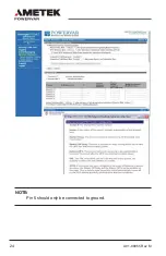
Page 24: ...24 A01 00055 Rev M NOTE Pin 5 should only be connected to ground ...

Page 25: ...mplete you can still start the UPM to test its operation and the operation of your system using Start Manager With the UPM off follow these simple steps 1 Disconnect the input AC power cable from the AC mains 2 Ensure that the batteries are connected behind the front panel 3 Press and hold the On Off switch on the front panel until the UPM beeps 4 The UPM is now running on battery When you have fi...

Page 26: ...rature the battery should be recharged every two months The UPM does not need to be turned on for charging to occur it only needs to be plugged in with batteries connected Batteries must be disconnected when changing cycle is complete and UPM is returned to storage NOTE This product is not designed for continuous use on batteries UPM should always be plugged in to AC mains voltage when not being u...

Page 27: ... acid These batteries use a non liquid electrolyte which makes it possible to use them in any physical orientation The batteries are designed to last from two to five years Their actual life span will depend on several factors including how often power outages occur how long power outages last and the temperature of the environment in which the UPM operates Frequent long duration power outages wil...

Page 28: ...nly the battery assembly in this unit is user serviceable non medical units only The battery compartment is accessed by removing the front panel as described in the following instructions No other user serviceable parts are contained in this UPM Do not remove any cover other than the front battery access panels A battery even a depleted one can deliver very high currents when short circuited There...

Page 29: ...the batteries in this UPM is designed to be a safe and simple procedure Batteries may be replaced while the UPM is on and providing power to the connected load You should remember however that if a power outage occurs after the old batteries are disconnected and before the new batteries are installed power will be lost to your connected system and components CAUTION RISK OF EXPLOSION IF BATTERY IS...

Page 30: ... of electrical shock and high short circuit current The following precautions should be observed when working with batteries Remove watches rings or other metal objects Use tools with insulated handles Wear rubber gloves and boots Do not lay tools or metal parts on top of batteries Disconnect the charging source prior to connecting or disconnecting battery terminals Determine if battery is inadver...

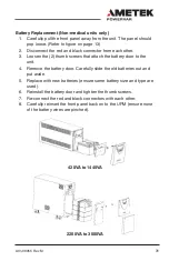
Page 31: ...screws that attach the battery door to the unit 4 Remove the battery door Carefully slide the old batteries out and put aside 5 Replace with new batteries ensure same battery size and type are used 6 Reinstall the battery door and tighten the thumb screws 7 Re connect the red and black connectors with each other 8 Carefully reinsert the front panel back on to the UPM ensure none of the battery wir...

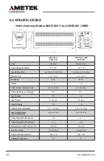
Page 32: ...TU Hr 140 140 T H D w 100 Resistive Load 4 On Battery 4 On Battery Online Efficiency w o Charger 90 90 Input Voltage 120 120 Input Current 5 18 Amps 5 18 Amps Output Voltage 120 120 Output Current VA Watts 3 50 3 20 Amps 3 50 3 20 Amps Input Voltage Range w o Using Battery 96 to 144 Volts 96 to 144 Volts Output Regulation On Mains 10 10 Output Regulation On Battery 5 5 Backup Time at Full Load 0 7...

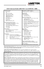
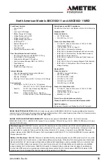
Page 33: ... Device CISPR11 2009 A1 2010 Class A EN60601 1 2 2007 Note Class B is Available as an Option Please Consult Your Powervar Sales Representative RoHS Compliance All Products Standard and Medical are RoHS Compliant North American Models ABCE422 11 and ABCE422 11MED Warranty Support AMETEK Powervar warrants the electronics and transformers used in its uninterruptible power man agers to be free from de...

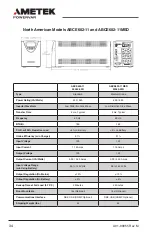
Page 34: ...0 Resistive Load 4 on Battery 4 on Battery Online Efficiency w o Charger 91 91 Input Voltage 120 120 Input Current 7 16 Amps 7 16 Amps Output Voltage 120 120 Output Current VA Watts 5 00 4 50 Amps 5 00 4 50 Amps Input Voltage Range w o Using Battery 96 to 144 Volts 96 to 144 Volts Output Regulation On Mains 10 10 Output Regulation On Battery 5 5 Backup Time at Full Load 0 7 P F 5 Minutes 5 Minutes...

Page 35: ...ss A Digital Device CISPR11 2009 A1 2010 Class A EN60601 1 2 2007 Note Class B is Available as an Option Please Consult Your Powervar Sales Representative RoHS Compliance All products Standard and Medical are RoHS Compliant North American Models ABCE602 11 and ABCE602 11MED Warranty Support AMETEK Powervar warrants the electronics and transformers used in its uninterruptible power man agers to be ...

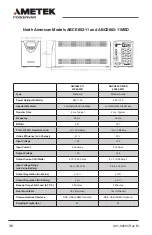
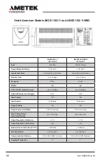
Page 36: ...0 Resistive Load 4 on Battery 4 on Battery Online Efficiency w o Charger 91 91 Input Voltage 120 120 Input Current 9 35 Amps 9 35 Amps Output Voltage 120 120 Output Current VA Watts 6 70 6 00 Amps 6 70 6 00 Amps Input Voltage Range w o Using Battery 96 to 144 Volts 96 to 144 Volts Output Regulation On Mains 10 10 Output Regulation On Battery 5 5 Backup Time at Full Load 0 7 P F 5 Minutes 5 Minutes...

Page 37: ...ss A Digital Device CISPR11 2009 A1 2010 Class A EN60601 1 2 2007 Note Class B is Available as an Option Please Consult Your Powervar Sales Representative RoHS Compliance All products Standard and Medical are RoHS Compliant North American Models ABCE802 11 and ABCE802 11MED Warranty Support AMETEK Powervar warrants the electronics and transformers used in its uninterruptible power man agers to be ...

Page 38: ...100 Resistive Load 4 on Battery 4 on Battery Online Efficiency w o Charger 90 90 Input Voltage 120 120 Input Current 12 00 Amps 12 00 Amps Output Voltage 120 120 Output Current VA Watts 9 20 8 25 Amps 9 20 8 25 Amps Input Voltage Range w o Using Battery 96 to 144 Volts 96 to 144 Volts Output Regulation On Mains 10 10 Output Regulation On battery 5 5 Backup Time at Full Load 0 7 P F 5 Minutes 5 Min...

Page 39: ...ss A Digital Device CISPR11 2009 A1 2010 Class A EN60601 1 2 2007 Note Class B is Available as an Option Please Consult Your Powervar Sales Representative RoHS Compliance All products Standard and Medical are RoHS Compliant North American Models ABCE1102 11 and ABCE1102 11MED Warranty Support AMETEK Powervar warrants the electronics and transformers used in its uninterruptible power man agers to b...

Page 40: ...00 Resistive Load 4 on Battery 4 on Battery Online Efficiency w o Charger 91 91 Input Voltage 120 120 Input Current 12 00 Amps 12 00 Amps Output Voltage 120 120 Output Current VA Watts 12 00 10 80 Amps 12 00 10 80 Amps Input Voltage Range w o Using Battery 96 to 144 Volts 96 to 144 Volts Output Regulation On Mains 10 10 Output Regulation On battery 5 5 Backup Time at Full Load 0 7 P F 5 Minutes 5 ...

Page 41: ...ss A Digital Device CISPR11 2009 A1 2010 Class A EN60601 1 2 2007 Note Class B is Available as an Option Please Consult Your Powervar Sales Representative RoHS Compliance All products Standard and Medical are RoHS Compliant North American Models ABCE1442 11 and ABCE1442 11MED Warranty Support AMETEK Powervar warrants the electronics and transformers used in its uninterruptible power man agers to b...

Page 42: ...120 120 Input Current 16 0 Amps 16 0 Amps Output Voltage 120 120 Output Current VA Watts 15 0 13 5 Amps 15 0 13 5 Amps Input Voltage Range w o Using Battery 96 to 144 volts 96 to 144 volts Output Regulation Mains 10 10 Output Regulation On Battery 5 5 Backup Time at Full Load 0 7 P F 5 Minutes 5 Minutes Floor Mountable Yes Optional Yes Optional Communications Interface DB9 USB SNMP Optional DB9 US...

Page 43: ...tion Please Consult Your Powervar Sales Representative RoHS Compliance All products Standard and Medical are RoHS Compliant North American Models ABCE2202 11 and ABCE3002 11 Warranty Support AMETEK Powervar warrants the electronics and transformers used in its uninterruptible power man agers to be free from defects in materials and workmanship for a period of five years from the date of shipment B...

Page 44: ... 120 120 Input Current 24 0 Amps 24 0 Amps Output Voltage 120 120 Output Current VA Watts 18 5 16 5 Amps 23 0 20 7Amps Input Voltage Range w o Using Battery 96 to 144 volts 96 to 144 volts Output Regulation Mains 10 10 Output Regulation On Battery 5 5 Backup Time at Full Load 0 7 P F 5 Minutes 5 Minutes Floor Mountable Yes Optional Yes Optional Communications Interface DB9 USB SNMP Optional DB9 US...

Page 45: ...ption Please Consult Your Powervar Sales Representative RoHS Compliance All products Standard and Medical are RoHS Compliant North American Models ABCE2202 11 and ABCE3002 11 Warranty Support AMETEK Powervar warrants the electronics and transformers used in its uninterruptible power man agers to be free from defects in materials and workmanship for a period of five years from the date of shipment ...

Page 46: ...40 T H D w 100 Resistive Load 4 On Battery 4 On Battery Online Efficiency w o Charger 90 90 Input Voltage 230 230 Input Current 2 70 Amps 2 70 Amps Output Voltage 230 230 Output Current VA Watts 1 85 1 65 Amps 1 85 1 65 Amps Input Voltage Range w o Using Battery 185 to 276 Volts 185 to 276 Volts Output Regulation On Mains 10 10 Output Regulation On Battery 5 5 Backup Time at Full Load 0 7 P F 5 Mi...

Page 47: ...ce CISPR11 2009 A1 2010 Class A EN60601 1 2 2007 Note Class B is Available as an Option Please Consult Your Powervar Sales Representative RoHS Compliance All products Standard and Medical are RoHS Compliant International Models ABCE422 22 and ABCE422 22MED Warranty Support AMETEK Powervar warrants the electronics and transformers used in its uninterruptible power man agers to be free from defects ...

Page 48: ... Resistive Load 4 on Battery 4 on Battery Online Efficiency w o Charger 92 92 Input Voltage 230 230 Input Current 3 73 Amps 3 73 Amps Output Voltage 230 230 Output Current VA Watts 2 60 2 35 Amps 2 60 2 35 Amps Input Voltage Range w o Using Battery 185 to 276 Volts 185 to 276 Volts Output Regulation On Mains 10 10 Output Regulation On Battery 5 5 Backup Time at Full Load 0 7 P F 5 Minutes 5 Minute...

Page 49: ... Digital Device CISPR11 2009 A1 2010 Class A EN60601 1 2 2007 Note Class B is Available as an Option Please Consult Your Powervar Sales Representative RoHS Compliance All products Standard and Medical are RoHS Compliant International Models ABCE602 22 and ABCE602 22MED Warranty Support AMETEK Powervar warrants the electronics and transformers used in its uninterruptible power man agers to be free ...

Page 50: ...100 Resistive Load 4 on Battery 4 on Battery Online Efficiency w o Charger 92 92 Input Voltage 230 230 Input Current 4 88 Amps 4 88 Amps Output Voltage 230 230 Output Current VA Watts 3 50 3 15 Amps 3 50 3 15 Amps Input Voltage Range w o Using Battery 185 to 276 Volts 185 to 276 Volts Output Regulation On Mains 10 10 Output Regulation On Battery 5 5 Backup Time at Full Load 0 7 P F 5 Minutes 5 Min...

Page 51: ...Digital Device CISPR11 2009 A1 2010 Class A EN60601 1 2 2007 Note Class B is Available as an Option Please Consult Your Powervar Sales Representative RoHS Compliance All products Standard and Medical are RoHS Compliant International Models ABCE802 22 and ABCE802 22MED Warranty Support AMETEK Powervar warrants the electronics and transformers used in its uninterruptible power man agers to be free f...

Page 52: ... D w 100 Resistive Load 4 on Battery 4 on Battery Online Efficiency w o Charger 93 93 Input Voltage 230 230 Input Current 8 10 Amps 8 10 Amps Output Voltage 230 230 Output Current VA Watts 4 80 4 30 Amps 4 80 4 30 Amps Input Voltage Range w o Using Battery 185 to 276 volts 185 to 276 volts Output Regulation Mains 10 10 Output Regulation On Battery 5 5 Backup Time at Full Load 0 7 P F 5 Minutes 5 M...

Page 53: ...Digital Device CISPR11 2009 A1 2010 Class A EN60601 1 2 2007 Note Class B is Available as an Option Please Consult Your Powervar Sales Representative RoHS Compliance All products Standard and Medical are RoHS Compliant International Models ABCE1102 22 and ABCE1102 22MED Warranty Support AMETEK Powervar warrants the electronics and transformers used in its uninterruptible power man agers to be free...

Page 54: ...H D w 100 Resistive Load 4 on Battery 4 on Battery Online Efficiency w o Charger 94 94 Input Voltage 230 230 Input Current 8 54 Amps 8 54 Amps Output Voltage 230 230 Output Current VA Watts 6 30 5 65 Amps 6 30 5 65 Amps Input Voltage Range w o Using Battery 185 to 276 volts 185 to 276 volts Output Regulation Mains 10 10 Output Regulation On Battery 5 5 Backup Time at Full Load 0 7 P F 5 Minutes 5 ...

Page 55: ...Digital Device CISPR11 2009 A1 2010 Class A EN60601 1 2 2007 Note Class B is Available as an Option Please Consult Your Powervar Sales Representative RoHS Compliance All products Standard and Medical are RoHS Compliant International Models ABCE1442 22 and ABCE1442 22MED Warranty Support AMETEK Powervar warrants the electronics and transformers used in its uninterruptible power man agers to be free...

Page 56: ...0 230 Input Current 16 0 Amps 16 0 Amps Output Voltage 230 230 Output Current VA Watts 9 55 8 60 Amps 9 55 8 60 Amps Input Voltage Range w o Using Battery 185 to 276 Volts 185 to 276 Volts Output Regulation Mains 10 10 Output Regulation On Battery 5 5 Backup Time at Full Load 0 7 P F 5 Minutes 5 Minutes Floor Mountable Yes Optional Yes Optional Communications Interface DB9 USB SNMP Optional DB9 US...

Page 57: ...2009 A1 2010 Class A EN60601 1 2 2007 Note Class B is Available as an Option Please Consult Your Powervar Sales Representative RoHS Compliance All products Standard and Medical are RoHS Compliant International Models ABCE2202 22 and ABCE2202 22MED Warranty Support AMETEK Powervar warrants the electronics and transformers used in its uninterruptible power man agers to be free from defects in materi...

Page 58: ...urrent 16 0 Amps 16 0 Amps Output Voltage 230 230 Output Current VA Watts 13 0 11 75 Amps 13 0 11 75 Amps Input Voltage Range w o Using Battery 185 to 276 Volts 185 to 276 Volts Output Regulation Mains 10 10 Output Regulation On Battery 5 5 Backup Time at Full Load 0 7 P F 5 Minutes 5 Minutes Floor Mountable Yes Optional Yes Optional Communications Interface DB9 USB SNMP Optional DB9 USB SNMP Opti...

Page 59: ...2009 A1 2010 Class A EN60601 1 2 2007 Note Class B is Available as an Option Please Consult Your Powervar Sales Representative RoHS Compliance All products Standard and Medical are RoHS Compliant International Models ABCE3002 22 and ABCE3002 22MED Warranty Support AMETEK Powervar warrants the electronics and transformers used in its uninterruptible power man agers to be free from defects in materi...

Page 60: ...ircuit breaker is tripped 1 Press and hold the On Off switch for 3 seconds min 2 Check wall socket and test for proper line voltage 3 Plug in input power cord 4 Reduce load and reset circuit breaker UPM Overload LED s are illuminated and continuous audible alarm sounds UPM is overload Reduce load by removing the least critical load items from the UPM output Low Replace Battery LED is illuminated B...

Page 61: ...ED 250 VAC 8 0 A ABCE1442 11MED 250 VAC 12 5 A ABCE1442 22MED 250 VAC 8 0 A 2200 and 3000 VA units have resettable output circuit breaker Technical Support AMETEK Powervar provides technical product support during our regular business hours of 8 00 a m to 5 00 p m Between the hours of 5 00 p m and 8 00 a m our phone system will allow you to leave a message for our technical support department The ...

Page 62: ...ries This warranty is limited to repairing replacing or refurbishing at AMETEK Powervar s option any defective component circuit board or module within the Product This warranty is limited to AMETEK Powervar depot service Refer to AMETEK Powervar Warranty Statement for complete details Life Support AMETEK Powervar does not recommend the use of our UPM products on life support equipment where the f...

Page 63: ...és constamment au secteur sauf lors des pannes de courant Les produits débranchés régulièrement et intentionnellement du secteur verront la durée de vie de leur batterie réduite de façon notable La clause de garantie standard d AMETEK Powervar ne s applique pas dans ces cas là et elle est remplacée par une garantie de 90 jours à partir de la date d expédition d AMETEK Powervar La garantie fournie ...

Page 64: ...ipement D autres symboles d avertissement peuvent apparaître en plus des symboles Danger et Attention et sont utilisés pour identifier des dangers spéciaux Ces avertissements concernent des domaines particuliers qui demandent une attention et ou des procédures spéciales afin d éviter des blessures importantes voire la mort Avertissements électriques Le symbole d avertissement électrique est un écl...

Page 65: ...pe d assistance technique par téléphone au 1 800 369 7179 ou nous écrire à servicerma powervar com AMETEK Powervar est un fournisseur mondial de solutions de gestion de l énergie dont le siège est à Waukegan Illinois avec des ventes internationales et des bureaux de distribution à Swindon Royaume Uni Toronto Canada Mexico Mexique et en Allemagne Toutes les solutions d AMETEK Powervar incorporent u...

Page 66: ...e de batteries que ceux utilisés par AMETEK Powervar Les batteries utilisées dans cet UPM sont des batteries étanches au plomb acide sans entretien La disposition des batteries doit être faite de manière correcte Reportez vous à vos codes locaux pour la disposition des batteries Modele UPM Quantité et type de batterie 420 VA 2 X 21W 12 VOLT 600 VA 2 X 34W 12 VOLT 800 VA 2 X 34W 12 VOLT 1100 VA 4 X...

Page 67: ...rait annuler la garantie REMARQUE L UPM est prévu pour une utilisation stationnaire Si l UPM est intégré à un panier mobile il doit être fixé au panier et testé dans l application par l utilisateur final L UPM n est pas prévu pour le contact avec le patient ou pour une installation susceptible de provoquer un contact accidentel avec les patients Ne pas utiliser cet UPM pour les applications de sou...

Page 68: ...médicales Ne doit pas être utilisé dans une salle informatique définie par la norme ANSI NFPA 75 sur la protection des ordinateurs et des équipements électroniques de traitement des données La prise de sortie doit être installée près de l équipement et doit être facilement accessible La batterie doit être déconnectée de l UPM en la débranchant au niveau de ses connexions rapides si des travaux d e...

Page 69: ...peut causer des interférences préjudiciables aux communications radio Toutefois il n existe aucune garantie que ces interférences n interviendront pas dans une installation particulière Si cet équipement crée des interférences nuisibles dans la réception de la radio ou de la télévision ce qui peut être identifié en allumant et éteignant l UPM l utilisateur est invité à essayer de les corriger en s...

Page 70: ...ur dommages lors de l expédition 1 Déposez la auprès du transporteur dans les 15 jours suivants la réception de l équipement 2 Envoyez à votre représentant de service une copie de la réclamation pour dommages dans un délai de 15 jours REMARQUE Vérifiez la date de recharge de la batterie sur l étiquette du carton d emballage Si la date est dépassée et si les batteries n ont jamais été rechargées n ...

Page 71: ...branchement des batteries avant de démarrer le UPM Si vous devez expédier le UPM dans un autre endroit il faundra déconnecter les batteries par sécurité 1 Retirez ie UPS de la boîte 3 Retirez le couvercle en façade et branchez le connecteur 2 Retirez le UPS de laboîte 4 Remettre le couvercle et retirez le collant jaune 5 Appuyez pendant 3 secondes pour démarrer le UPM SECURITY II Guide de démmarge...

Page 72: ... 3 Conservez le carton pour une utilisationfuture Placez l appareil dans une zone protégée suffisamment ventilée exempte d humidité de gaz inflammable et de corrosion REMARQUE Avant l installation veuillez lire et comprendre les instructions suivantes Vérifiez bien que le carton n est pas endommagé En cas de dommages avisez immédiatement le transporteur Conservez le carton au cas où vous devriez e...

Page 73: ...rifiez que le voyant de défaut de câblage du site est éteint modèles à 120 VCA uniquement Une fois le branchement correctement effectué et après vérification allumez l UPM en appuyant sur l interrupteur marche arrêt On Off du panneau avant et maintenez le enfoncé pendant 3 secondes REMARQUE Pour utiliser l UPM vous devez d abord brancher la ou les prises d activation de la batterie dans le ou les ...

Page 74: ...ries en trouble ou déconnectées UPM en correction due à un voltage trop élevé UPM en correction due à un voltage trop bas Faute UPM en surchauffe Voyants de charge et de batterie de l UPM Affichage UPM indiquant un fonctionnement normal Batter ies complètement chargées avec une charge de 60 indiquée Affichage UPM indiquant un fonctionnement sur la batterie de secours Batteries chargées à 80 avec u...

Page 75: ...n d alimentation de l UPM Si vous décidez de tester l UPM de cette façon vous observerez que l UPM émettra un bip à quelques secondes d intervalle tant que le cordon sera débranché Le voyant de la batterie s allumera aussi constamment Une fois le test initial de la fonction de secours de l UPM effectué allumez l équipement informatique connecté Vérifiez que l appareil n est pas surchargé Si l appa...

Page 76: ...e il effectuera un test automatique de la batterie tous les six jours Si vous utilisez le logiciel MopUPS Express vous pouvez configurer le système pour effectuer ce test automatiquement périodiquement L UPM est expédié avec une batterie chargée mais il est normal qu elle se décharge partiellement pendant l entreposage et l expédition Vous pouvez utiliser l UPM immédiatement mais vous devez savoir...

Page 77: ...l teste à la fois la batterie et l inverseur pendant quelques secondes avant de retourner à l alimentation CA Nous recommandons de fermer tous les fichiers ouverts avant de démarrer un autotest Lorsque l alimentation CA tombe en panne l UPM vous alerte avec une alarme sonore Le bouton de Test Silence est utilisé pour couper l alarme Lorsque la charge de la batterie commence à baisser l alarme sono...

Page 78: ...teur 3 pôles 2 pôles souvent appelé tricheur avec l UPM Ces dispositifs suppriment la connexion de sécurité à la terre de l UPM et feront s allumer la DEL de défaut de câblage de site MopUPS Pro Les communications intelligentes AMETEK Powervar vous donnent plusieurs options pour Protection des données sur un ordinateur alimenté par UPM lorsque la batterie est faible Surveillance de l UPM pour perm...

Page 79: ...M et accéder aux informations de fonctionnement de l UPM En utilisant le logiciel vous pouvez visualiser des paramètres comme les tensions CA d entrée et de sortie la fréquence de la ligne d alimentation et la tension de la batterie Pour prendre en charge ces fonctions sans la suite logicielle MopUPS Pro vous devrez soit acheter ou construire votre propre câble spécial Le tableau suivant décrit l ...

Page 80: ...pas terminé vous pouvez malgré tout mettre en marche l UPM pour tester son fonctionnement et celui de votre système à l aide du gestionnaire de démarrage Avec l UPM éteint suivez ces étapes simples 1 Débranchez le câble d alimentation CA de l alimentation secteur 2 Assurez vous que les batteries sont connectées derrière le panneau avant 3 Appuyez sur le commutateur On Off sur le panneau avant et m...

Page 81: ... batterie L UPM doit toujours être branché à la tension de secteur lorsqu il n est pas utilisé en mode batterie de secours pour éviter d endommager les batteries internes entraînant un dysfonctionnement de la batterie p ex surchauffe ou incapacité à conserver la charge Le microprogramme de l UPM dans cette unité fournit un avertissement et une alerte supplémentaires pour empêcher et détecter cette...

Page 82: ...qui permet de les utiliser dans n importe quelle orientation physique Les batteries sont conçues pour durer de deux à cinq ans Leur durée de vie réelle dépendra de plusieurs facteurs dont la fréquence des pannes de courant la durée des pannes de courant et la température de l environnement dans lequel l UPM fonctionne Les pannes de courant fréquentes et longues réduiront la durée de vie de la batt...

Page 83: ...sonne qui n y est pas autorisée ou qui est incapable de suivre ces consignes ATTENTION Seul le bloc batterie est remplaçable par l utilisateur dans cet appareil appareils non médicaux en bon état uniquement Le compartiment des batteries est accessible en enlevant le panneau avant selon les instructions suivantes Il n existe aucun autre élément dans cet UPM qui puisse être remplacé par l utilisateu...

Page 84: ...rèves et rares Avec l UPM le remplacement de la batterie par l utilisateur est rapide et facile Il n est pas nécessaire d éteindre l UPM ou le système y connecté L UPM permet de changer la batterie à chaud pendant que le système fonctionne REMARQUE Le changement des batteries dans cet UPM est conçu comme une procédure sûre et simple Les batteries peuvent être remplacées pendant que l UPM est allum...

Page 85: ...ovoquer des brûlures graves ATTENTION Ne pas jeter les batteries au feu Les batteries peuvent exploser ATTENTION Ne pas ouvrir ou endommager les batteries La substance libérée est dangereuse pour la peau et les yeux Elle peut être toxique Une batterie peut présenter un risque de décharge électrique et de courant de court circuit de forte intensité Les précautions suivantes doivent être prises lors...

Page 86: ... est pas mise à la terre par inadvertance Si elle est mise à la terre retirez la source de terre Le contact avec une batterie mise à la terre peut entraîner une électrocution REMARQUE Si vous avez lu et compris les avertissements précédant cette section vous pouvez procéder comme suit ...

Page 87: ...ttachent la porte de la batterie à l appareil 6 Retirez la porte de la batterie Sortez la vieille batterie en la faisant glisser avec précaution et mettez la de côté 7 Remplacez la par une nouvelle batterie assurez vous d utiliser la même taille et type de batterie 8 Réinstallez la porte de la batterie et serrez les vis à ailettes 9 Reconnectez les connecteurs rouge et noir 10 Remettez soigneuseme...

Page 88: ...nd oder Sachbeschädigungen verursachen können Andere Warnsymbole können neben den Symbolen Gefahr und Vorsicht verwendet werden um besondere Gefahren anzuzeigen Diese Warnhinweise beschreiben besondere Bereiche in denen spezielle Vorsichtsmaßnahmen oder Verfahren erforderlich sind um schwere und möglicherweise tödliche Verletzungen zu vermeiden Gefährliche elektrische Spannung Das elektrische Warn...

Page 89: ...n die AC Netzversorgung angeschlossen sind Bei Produkten die regelmäßig und absichtlich von der AC Netzversorgung getrennt werden reduziert sich die Batterielebensdauer erheblich AMETEK Powervars standardmäßige Garantiefrist ist in diesen Fällen nicht anwendbar und wird durch eine 90 tägige Garantiefrist ab dem Versanddatum von AMETEK Powervar ersetzt Die von AMETEK Powervar bereitgestellte Garant...

Page 90: ...en haben können Sie sich jederzeit telefonisch 1 800 369 7179 oder per E Mail rma powervar ametek com an unser technisches Supportteam wenden AMETEK Powervar ist ein weltweiter Anbieter von Leistungsmanagementlösungen mit Hauptsitze in Waukegan Illinois USA und internationalen Vertriebs und Handelsniederlassungen in Großbritannien Kanada Mexiko und Deutschland Alle Lösungen von AMETEK Powervar bei...

Page 91: ...rien wie die von AMETEK Powervar verwendeten Bei den in diesem UPM verwendeten Batterien handelt es sich um wartungsfreie Blei Säure Batterien Batterien müssen ordnungsgemäß entsorgt werden Bitte beachten Sie die örtlichen Bestimmungen zur korrekten Entsorgung von Batterien UPM Leistung Menge und Batterieleistung 420 VA 2 X 21W 12 VOLT 600 VA 2 X 34W 12 VOLT 800 VA 2 X 34W 12 VOLT 1100 VA 4 X 34W ...

Page 92: ...nahmen Eine Nichtbefolgung dieser Maßnahmen könnte die Garantie aufheben HINWEIS Der UPM ist eigentlich für stationären Betrieb ausgelegt Wenn der UPM dennoch auf einem mobilen Transportwagen betrieben wird muss er entsprechend gesichert und zusammen mit dem Gesamtsystem durch den Endanwender geprüft werden Dieser UPM Gerät ist für den Einsatz in Patientenumgebungen bestimmt Powervar Produkte sind...

Page 93: ...tenden Verunreinigungen bestimmt Die Wechselstromquelle des UPM Geräts sollte sich in bequemer Nähe zum UPM Gerät befinden und leicht zugänglich sein vermeiden Sie bei der Versorgung des UPM Geräts Verlängerungskabel oder temporäre Steckerleisten Der Gesamtableitstrom des UPM Geräts und der angeschlossenen Verbrauchergeräte sollte 3 5 mA bei nicht medizinischen Geräten nicht überschreiten Nicht zu...

Page 94: ...zten Gebieten gewährleisten Dieses Gerät erzeugt nutzt und emittiert Hochfrequenzstrahlung und kann sich bei einer nicht den Anweisungen entsprechenden Installation und Verwendung negativ auf den Funkverkehr auswirken Es kann jedoch nicht gewährleistet werden dass bei bestimmten Installationen keine Interferenzen auftreten Sollte das Gerät Störungen im Rundfunk und Fernsehempfang verursachen was d...

Page 95: ...chaden wie nachstehend angegeben 1 Melden Sie den Schaden innerhalb von 15 Tagen nach Erhalt der Ausrüstungen dem Spediteur 2 Senden Sie eine Kopie der Schadensmeldung innerhalb von 15 Tagen an Ihren Service Vertreter HINWEIS Prüfen Sie das Batterieaufladedatum auf dem Aufkleber des Versandkartons Falls das Datum abgelaufen ist und die Batterien nie aufgeladen wurden verwenden Sie das UPM Gerät ni...

Page 96: ...96 A01 00055 Rev M Kurzanleitung Security II Kurzanleitung ...

Page 97: ...dungszwecke aufbewahren Stellen Sie das Gerät in einem geschützten Bereich mit einer angemessenen Luftzufuhr und ohne Feuchtigkeit entzündlichen Gasen und Korrosion auf HINWEIS Bitte lesen Sie vor dem Anschluss die folgenden Anleitungen Prüfen Sie den Karton sorgfältig auf Beschädigungen Benachrichtigen Sie den Spediteur umgehend falls Schäden festgestellt werden Bewahren Sie den Karton unbedingt ...

Page 98: ... dreipoligen Steckdose an Stellen Sie sicher dass Anzeige eines Standortverdrahtungsfehlers SF nicht leuchtet nur 120 VAC Modelle Schalten Sie das ordnungsgemäß angeschlossene und grundsätzlich geprüfte UPM Gerät ein indem Sie den Ein Aus Schalter an der Frontblende 3 Sekunden lang gedrückt halten HINWEIS Zum Betrieb des UPM Geräte muss müssen zuerst der die Batterieaktivierungsstecker in die Batt...

Page 99: ...der AC Spannung UPM überlastet Batteriefehler oder Batterie getrennt Gerät im Buck Betrieb aufgrund hoher eingehender AC Spannung Gerät im Boost Betrieb aufgrund hoher eingehender AC Spannung Fehler UPM über Temperatur UPM Last und Batterieanzeigen UPM Display zeigt normalen Betrieb an Batterien voll geladen mit 60 iger Lastanzeige UPM Display zeigt Batterie im Backup Betrieb an Batterien zu 80 ge...

Page 100: ...Geräts abziehen Wenn Sie das UPM Gerät auf diese Weise prüfen werden Sie feststellen dass diese alle paar Sekunden piept während das Netzkabel getrennt ist Außerdem leuchtet die Batterie LED durchgehend Schalten Sie nach der Erstprüfung der Backup Funktion des UPM Geräts die angeschlossenen Computerausrüstungen ein Prüfen Sie dass das Gerät nicht überlastet ist Bei eine Überlastung des Geräts leuc...

Page 101: ...ttests durchführt Das UPM Gerät wird mit geladener Batterie versendet Während der Lagerung und des Versands tritt jedoch eine gewisse natürliche Entladung auf Sie können das UPM Gerät sofort einsetzen sollten jedoch bedenken dass die Backup Zeit eventuell geringer als der angegebene Nennwert ist bis die UPM Batterie mindestens sechs Stunden lang aufgeladen wurde AMETEK Powervar empfiehlt keine Las...

Page 102: ...tionssteuerung Wenn AC Strom vorhanden und das UPM Gerät in Betrieb ist wird das UPM Gerät durch Drücken der Taste Testen Stummschalten in den Selbsttestmodus versetzt in dem sowohl die Batterie als auch der Wechselrichter während einiger Sekunden getestet werden bevor das Gerät zur AC Versorgung zurückkehrt Wir empfehlen Ihnen vor dem Start des Selbsttests alle geöffneten Dateien zu schließen Bei...

Page 103: ...an der eine Brand oder Stromschlaggefahr darstellen könnte Eine fehlerhafte Verkabelung kann darüber hinaus zu Zuverlässigkeitsproblemen des UPM Geräts und des angeschlossenen Systems führen Verwenden Sie niemals einen Adapter zur Verwandlung eines Steckers mit 3 Stiften in einen 2 Stift Stecker auch als Cheater bezeichnet um das UPM Gerät an den Strom anzuschließen Dieser Vorrichtungen entfernen ...

Page 104: ...nd Linux http connectivity powervar com products mopups pro Szenario B Abschaltung von mehr als einem Computer die dieselbe UPM Ausgangsleistung nutzen oder im Falle von Anwendungen bei denen einer der Computer mehr als 1 82 Meter vom UPM Gerät entfernt ist Kaufen Sie den optionalen ManageUPS Netzadapter SNMP WEB Karte Art Nr AM P1 R2 installieren Sie diesen im Schlitz Erweiterte Kommunikationen d...

Page 105: ...n Sie jedoch den ManageUPS Netzadapter mit Umgebungssensor Art Nr AME P1 R2 http connectivity powervar com products manageups pe Szenario D Automatische Abschaltung eins Alt oder firmenintern entwickelten Systems das dazu ausgelegt ist mit USV Statusinformationen gekoppelt zu werden die als Relaiskontaktschluss oder aktive hohe niedrige 12 V Signalen angezeigt werden Falls Ihr System mit simuliert...

Page 106: ...ter SNMP WEB Karte Art Nr AM P1 R2 installieren Sie diesen im Schlitz Erweiterte Kommunikationen des UPM Geräts und verbinden Sie dieses mit dem TCP IP LAN mit dem die Computer verbunden sind Konfigurieren Sie den eingebetteten E Mail Client im Adapter um auf einen SMTP Server Ihres Unternehmensnetzwerks zuzugreifen und Alarmbenachrichtigungen an E Mail Empfänger zu senden Informationen und die Be...

Page 107: ...mit Ihrem Unternehmensnetzwerk zu verbinden Kaufen Sie eine Lizenz für das Softwareprodukt ManageUPS CIO laden Sie die Software herunter und installieren Sie diese auf einem Server der Klasse VM oder physischen Host Computer in Ihren Unternehmensnetzwerk Informationen Benutzerhandbuch und Installationspakete für CIO finden Sie unter diesem Link http connectivity powervar com products manageups cio...

Page 108: ...schaltung über den WEB Browser um spezifische Lasten des UPM Geräts neu zu starten oder zu steuern Der nachstehende Screenshot zeigt das Hauptmenü über das die Steuerungen der integrierten geschalteten PDU aufgerufen werden AUTOMATISIERTER LASTABWURF UM BATTERIELEISTUNG FÜR ANDERE LASTEN ZU SPAREN Der nachstehende Screenshot zeigt das Hauptmenü der WEB Schnittstelle des ManageUPS Netzadapters um d...

Page 109: ...erte Abschaltungs und Neustartverzögerungen über die WEB Schnittstelle des ManageUPS Netzadapters für jede Buchsengruppen konfiguriert werden können Beachten Sie dass die Steuerung der Batterieabschaltungsverzögerung über die Funktion Steuerung der Netzwerkabschaltung konfiguriert wird falls die Last an einer Buchse ein Computer ist der zwecks Daten oder Systemintegrität normal heruntergefahren we...

Page 110: ...t der Erde verbunden sein HINWEIS Sie können natürlich Ihren Computer mit dem UPM Gerät verbinden ohne Software zu verwenden Bei einem Ausfall der Netzversorgung piept das UPM Gerät und Sie müssen dann den Computer und das UPM Gerät manuell abschalten ...

Page 111: ...s zu prüfen Führen Sie bei ausgeschaltetem UPM Gerät die folgenden einfachen Schritte durch 1 Das AC Eingangsnetzkabel vom AC Stromnetz trennen 2 Sicherstellen dass die Batterien hinter der Frontblende angeschlossen sind 3 Den Ein Aus Schalter an der Frontblende gedrückt halten bis das UPM Gerät piept 4 Das UPM Gerät wird jetzt über die Batterie betrieben Anschließend den Ein Aus Schalter erneut d...

Page 112: ...r UPM sollte möglichst immer an die Netzspannung angeschlossen sein wenn er nicht gerade im batteriegestützen Notstrombetrieb befindet Somit werden Schäden an den internen Batterien vermieden die dazu führen könnten dass diese nicht mehr ordnungsgemäß arbeitet z B Überhitzung oder dass die Batterie die Ladung nicht halten kann Die Firmware des UPM bietet einen zusätzlichen Warner und Alarm um eine...

Page 113: ...IGER HINWEIS Bei den in diesem UPM verwendeten Batterien handelt es sich um sogenannte Blei Säure Batterien Diese Batterien verwenden ein nicht flüssiges Elektrolyt sodass dies in jeder physischen Ausrichtung eingesetzt werden können Die Batterien sind auf eine Lebensdauer zwischen zwei und fünf Jahren ausgelegt Die tatsächliche Lebensdauer hängt von mehreren Faktoren ab darunter der Häufigkeit vo...

Page 114: ...Sie einen Austausch der Batterie vornehmen WARNUNG Die Wartung von Batterien sollte immer von einer Person durchgeführt oder überwacht werden welche die folgenden Vorsichtsmaßnahmen gelesen und verstanden hat und die mit der Akkus verbundenen Gefahren versteht Dieses Verfahren darf nicht von Personen durchgeführt werden die nicht befugt oder in der Lage sind diese Vorsichtsmaßnahmen zu befolgen VO...

Page 115: ... com bestellt werden Falls Sie Batterien von einer anderen Quelle erwerben stellen Sie unbedingt sicher dieselbe Art und Menge von Batterien zu verwenden Medizinische Geräte enthalten keine Bauteile die vom Anwender gewartet werden können Vom Anwender wechselbare Batterie nur nicht medizinische Geräte Früher oder später benötigt jedes UPM Gerät eine neue Batterie AMETEK Powervar geht von einer Leb...

Page 116: ... ein Stromausfall eintritt VORSICHT BEI ERSATZ DER BATTERIE DURCH EINEN UNGEEIGNETEN BATTERIETYP BESTEHT EXPLOSIONSGEFAHR Wenden Sie sich bezüglich des korrekten Batterieersatzkits beim Austausch der Batterie an Powervar Die entsprechenden Artikelnummern der Ersatzkits finden Sie nachstehend VA Leistung Art Nr Batterie Er satzkit 420 50842 01 600 800 50880 01 1100 1440 50814 01 2200 3000 50822 01 ...

Page 117: ...rwenden Gummihandschuhe und Schuhe mit Gummisohlen tragen Werkzeuge oder Metallteile nicht auf den Batterien ablegen Die Ladequelle vor dem Anschluss oder der Trennung von Batterieklemmen trennen Prüfen ob die Batterie unbemerkt geerdet wurde Im Falle einer versehentlichen Erdung die Stromquelle von der Erde trennen Die Berührung jedes Teils einer geerdeten Batterie kann einen Stromschlag verursac...

Page 118: ...befestigt ist 7 Die Batterieklappe entfernen Die alten Batterien vorsichtig herausgleiten lassen und zur Seite legen 8 Durch neue Batterien ersetzen sicherstellen Batterien derselben Größe und desselben Typs zu verwenden 9 Batterieklappe wieder anbringen und Rändelschrauben anziehen 10 Den roten und schwarzen Steckverbinder wieder miteinander verbinden 11 Die Frontblende vorsichtig wieder auf dem ...

Page 119: ...119 A01 00055 Rev M ...

Page 120: ...ntinuamente collegati all alimentazione in CA tranne durante le interruzioni dell alimentazione I prodotto regolarmente e intenzionalmente scollegati dall alimentazione in CA avranno una vita della batteria sensibilmente ridotta I termini della garanzia standard di AMETEK Powervar non si applicano in questi casi e sono sostituiti da una garanzia valida 90 giorni dal giorno della spedizione da AMET...

Page 121: ...ore e o danni all apparecchiatura Altri simboli possono comparire insieme a quelli di Pericolo e di Attenzione utilizzati per indicare particolari pericoli Questi simboli descrivono aree in cui sono necessarie particolari attenzioni e o procedure per prevenire gravi lesioni o la morte Avvertenze elettriche Il simbolo di avvertenza elettrica è il simbolo di un fulmine racchiuso in un triangolo Il s...

Page 122: ...di assistenza tecnica telefonicamente 1 800 369 7179 oppure via e mail all indirizzo rma powervar ametek com AMETEK Powervar è un fornitore globale di soluzioni per la gestione dell alimentazione con sede a Waukegan Illinois e uffici internazionali di vendita e distribuzione a Swindon Regno Unito Toronto Canada Città del Messico Messico e Germania Tutte le soluzioni AMETEK Powervar integrano un de...

Page 123: ...ate da AMETEK Powervar Le batterie utilizzate in questo UPM sono sigillate con piombo e acido e non richiedono manutenzione Le batterie devono essere smaltite adeguatamente Fare riferimento alle normative locali per lo smaltimento delle batterie Specifiche dell UPM Quantità e specifiche delle batterie 420 VA 2 X 21 W 12 VOLT 600 VA 2 X 34 W 12 VOLT 800 VA 2 X 34 W 12 VOLT 1100 VA 4 X 34 W 12 VOLT ...

Page 124: ... al carrello e collaudato per l applicazione desiderata dall utilizzatore finale Questo UPM è destinato ad essere utilizzato nelle vicinanze dei pazienti I prodotti AMETEK Powervar non sono destinati ad essere utilizzati in applicazioni intese a supportare o sostenere la vita Non utilizzare questo UPM per applicazioni di supporto alla vita nelle quali un malfunzionamento o un guasto dell UPM potre...

Page 125: ...ollegata dall UPM rilasciando i suoi connettori rapidi quando sia necessario effettuare operazioni di manutenzione o di riparazione all interno dell UPS e quando non collegata all alimentazione in CA Non smaltire le batterie incendiandole in quanto potrebbero esplodere Non aprire o manomettere le batterie Questo potrebbe comportare il rilascio di elettrolita o altre sostanze tossiche che potrebber...

Page 126: ...annose alle ricezioni radio e o televisive il che può essere determinato spegnendo e accendendo l apparecchiatura si consiglia all utilizzatore di provare a correggere l interferenza mediante una o più delle seguenti misure Spostare l UPM Spostare il carico Questo dispositivo è conforme alla Parte 15 delle regole FCC L utilizzo è soggetto alle seguenti due condizioni 1 Questo dispositivo non deve ...

Page 127: ...lamo per danno durante il trasporto 1 Presentarlo al corriere entro 15 giorni dal ricevimento dell apparecchiatura 2 Inviare una copia del reclamo per danni al proprio rappresentante dell assistenza entro 15 giorni NOTA Controllare la data di ricarica della batteria sull etichetta della confezione di spedizione Se la data è trascorsa e le batterie non sono mai state ricaricate non utilizzare l UPM...

Page 128: ...erruttore di accensione sul pannello frontale dell UPM Qualora successivamente si spedisca l UPM a un altra località scollegare prima i cavi delle batterie per garantire la sicurezza durante la spedizione 1 Rimuovere l UPM dalla confezione 3 Rimuovere il coperchio frontale dell UPM e collegare i connettori delle batterie 2 Collegare l UPM alla presa a muro 4 Reinstallare il coperchio anteriore e r...

Page 129: ...to flusso di aria e assenza di umidità gas infiammabili e agenti corrosivi NOTA Prima dell installazione leggere e comprendere le seguenti istruzioni Esaminare attentamente la confezione per verificare la presenza di danni Comunicare immediatamente al corriere eventuali danni rilevati Accertarsi di conservare la confezione nel caso in cui fosse necessario spedire l UPM per riparazioni o manutenzio...

Page 130: ...elli a 120 VCA Una volta correttamente collegato ed effettuati i controlli iniziali accendere l UPM premendo e tenendo premuto il pulsante di accensione spegnimento collocato sul pannello frontale per 3 secondi NOTA Dopo avere applicato l alimentazione all UPM occorre collegare le spine di attivazione della batteria nelle corrispondenti prese collocate dietro il pannello frontale per operare Da 42...

Page 131: ...ella batteria in incrementi del 20 Stato di carico dell UPM in incrementi del 20 L UPM funziona tramite la batteria a causa di una tensione di alimentazione non corretta UPM sovraccarico Guasto batteria o batteria non collegata Unità in funzionamento buck a causa di una elevata tensione CA in ingresso Unità in funzionamento boost a causa di una bassa tensione CA in ingresso Guasto UPM surriscaldat...

Page 132: ...ampeggino si tratta di un comportamento normale Avvio iniziale Con il sistema collegato e spento effettuare un test iniziale della funzione di backup dell UPM premendo il pulsante Test Silenzio collocato sul pannello frontale per 5 secondi Durante il test il LED Batteria sul pannello frontale dovrebbe accendersi brevemente È anche possibile effettuare il test della funzione di backup scollegando i...

Page 133: ...MopUPS Pro è possibile configurare il sistema in modo che effetui periodicamente un test automatico L UPM viene spedito con una batteria carica ma una perdita di carica si verifica naturalmente durante l immagazzinaggio e la spedizione È possibile iniziare a utilizzare l UPM immediatamente ma occorre sapere che il tempo di backup può essere inferiore a quello dichiarato fino a che la batteria non ...

Page 134: ...o ha una doppia funzione Premendo il pulsante Test Silenzio quando è presente alimentazione in CA e l UPM è in funzione l UPM entra nella modalità di test automatico in cui per alcuni secondi vengono testati sia la batteria che l invertitore prima di tornare all alimentazione in CA Si raccomanda di chiudere tutti i file aperti prima di avviare un test automatico In caso di interruzione dell alimen...

Page 135: ...ischio di incendio o di scossa elettrica Inoltre un cablaggio non corretto potrebbe potenzialmente creare problemi sia per l UPM che per il sistema ad esso collegato Non utilizzare mai un adattatore da 3 a 2 poli per alimentare l UPM Questi dispositivi eliminano dall UPM la connessione con la linea di terra e questo causerà l accensione del LED di Guasto del cablaggio FUNZIONI SPECIALI E OPZIONI I...

Page 136: ... di Comunicazione estesa dell UPM e collegarlo alla LAN TCP IP a cui sono collegati i computer Informazioni e la Guida per l utilizzatore dell adattatore di rete ManageUPS sono disponibili seguendo questo link http connectivity powervar com products manageups asp Acquistare una o più licenze del software MopUPS NSA Network Shutdown Agent scaricare NSA e installarlo su ognuno dei computer che di de...

Page 137: ...trollo industriali o con software di monitoraggio degli UPM legacy o open source in modo da attivare lo spegnimento automatico del computer in caso di bassa carica delle batterie La seguente tabella indica i segnali disponibili sui diversi pini della porta DB9 Definizione DB 9 per UPM Pin Descrizione 1 Bassa carica batteria Livello RS232 2 RS232 RX 3 RS232 TX 4 Spegnimento invertitore durante inte...

Page 138: ...onitoraggio dello stato dell UPM e della qualità dell alimentazione del sito tramite un BMS Building Monitoring System sistema di monitoraggio di edificio mediante MODBUS RTU o MODBUS TCP Utilizzare lo stesso motodo descritto sopra per gli Scenari A e B ma scegliere l adattatore di rete ManageUPS con servizi Modbus abilitati Codice AMB P1 R2 http connectivity powervar com products manageups pb SCE...

Page 139: ...rvar com products manageups asp Quando sul pannello posteriore dell UPM siano presenti gruppi di prese numerati questi gruppi possono essere attivati e disattivati da postazione remota mediante l interfaccia WEB oppure possono essere utilizzati con il Controller di shutdown di rete dell adattatore di rete ManageUPS per la rotazione dell erogazione o l avvio sequenziato Comando remoto di accensione...

Page 140: ...r configurare lo spegnimento automatico di specifici gruppi di prese della PDU switched integrata PROGRAMMAZIONE DI RITARDI DI RIAVVIO DIVERSI PER CONFIGURARE L ACCENSIONE AUTOMATICA AL TERMINE DI UNA INTERRUZIONE DI ALIMENTAZIONE Le videate seguenti illustrano come configurare i ritardi per lo spegnimento e il riavvio automatici per ciascun gruppo di prese tramite l interfaccia WEB dell adattator...

Page 141: ...resa sia un computer che necessita di uno spegnimento controllato per salvaguardare l integrità dei dati o del sistema è possibile controllare il ritardo dell interruzione dell alimentazione a batteria mediante la funzione di Controller shutdown di rete ...

Page 142: ... incompleto è comunque possibile avviare l UPM per testare il funzionamento dell UPM e del proprio sistema utilizzando il Gestore di avvio Con l UPM spento seguire questi semplici passi 1 Scollegare il cavo di alimentazione dalla presa 2 Accertarsi che dietro il pannello frontale le batterie siano collegate 3 Premere e tenuto premuto il pulsante di accensione spegnimento sul pannello frontale fino...

Page 143: ... deve essere ricaricata ogni due mesi Per ricaricare la batteria non occorre accendere l UPM è sufficiente sia alimentato mentre le batterie sono collegate Le batterie devono essere scollegate al termine della ricarica quando l UPM è riportato in magazzino NOTA Questo prodotto non è pensato per un utilizzo continuo a batteria L UPM deve essere sempre collegato all alimentazione CA quando non utili...

Page 144: ...no di un tipo speciale detto al piombo acido sigillate Queste batterie utilizzano un elettrolita non liquido che rende possibile utilizzarle in qualunque orientazione fisica Le batterie sono progettate per durare dai due ai cinque anni La durata effettiva dipende da diversi fattori fra cui la frequenza delle interruzioni dell alimentazione CA la durata di tali interruzioni e la temperatura dell am...

Page 145: ...orizzato o che sia incapace di seguire queste precauzioni ATTENZIONE In questa unità solo il gruppo batterie è manutenibile dall utilizzatore solo per unità non mediche È possibile accedere al vano batterie rimuovendo il pannello anteriore come riportato nelle seguenti istruzioni Nessun altro componente manutenibile dall utilizzatore è contenuto in questo UPM Non rimuovere alcun coperchio diverso ...

Page 146: ...aldo della batteria mentre il sistema è in funzione NOTA La sostituzione delle batterie dell UPM prevede una procedura semplice e sicura Le batterie possono essere sostituite mentre l UPM è acceso e fornisce alimentazione al carico collegato Occorre tuttavia ricordare che se dovesse manifestarsi una interruzione di alimentazione CA mentre le vecchie batterie sono scollegate e quelle nuove non sono...

Page 147: ...hio di scosse elettriche ed elevate correnti di cortocircuito Durante il lavoro con le batterie occorre osservare le seguenti precauzioni Rimuovere orologi anelli e altri oggetti metallici Utilizzare attrezzi con l impugnatura isolata Indossare stivali e guanti di gomma Non posare attrezzi o parti metalliche sulle batterie Scollegare la fonte di alimentazione prima di collegare o scollegare i term...

Page 148: ...gano lo sportello delle batterie all unità 4 Rimuovere lo sportello delle batterie Estrarre delicatamente ve vecchie batterie e metterle da parte 5 Sostituire con le nuove batterie accertarsi di utilizzare batterie dello stesso tipo e dimensione 6 Reinstallare lo sportello delle batterie e stringere le viti zigrinate 7 Ricollegare i connettori rosso e nero l uno con l altro 8 Inserire delicatament...

Page 149: ...149 A01 00055 Rev M ...

Page 150: ...kegan IL 60085 1 800 369 7179 P 847 596 7000 F 847 596 7100 Canada Address 700 Finley Avenue Unit 3 Ajax Ontario L1S 3Z2 P 905 239 9284 Europe Asia Address Unit 5 Birch Kembrey Park Swindon Wilts SN2 8UU UK P 44 1793 553980 F 44 1793 535350 Mexico Address Camino a la Montana No 178 101 PB4 Fracc Industrial La Perla 53340 Naucalpan Edo De Mexico P 52 55 5363 5448 ...

Reviews: