blue’Log X series
103 | 120
14.4.13
Q(cos
φ
(fix)) procedure
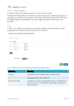
In this procedure the reactive power Q is used as control value. A constant cos
φ
displacement factor is used as the input value/target value. This input value is
converted into a specified percentage reactive power(Q) control value to allow use of
the generally greater inverter setting range with reactive power(Q) values. As a result,
the inverters can be regulated within a greater range.
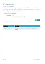
The target value is specified as a constant cos
φ
displacement factor value. To this end,
a configurable, constant value is saved. Using the active power P recorded at the grid
connection point by the selected measuring device, the specified constant
displacement factor (cos
φ)
is converted into a reactive power(Q) control value by the
data logger.
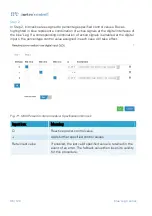
This procedure is configured in a similar manner to the cos
ϕ
(fix) procedure (cf. Section
This procedure requires a power quality analyzer that has been connected
to the data logger and configured.
14.4.14
Q(cos
φ
(P)) procedure
In this procedure a cos
φ
value is derived from the target value and is converted into
the reactive power Q as a control value to allow use of the generally greater inverter
setting range with reactive power(Q) values. As a result, the inverters can be regulated
within a greater range.
By changing the reactive power, the active power fed in at the grid connection point
can be influenced. To do this, the active power P fed in at the grid connection point is
recorded by the selected measuring device and transferred to the data logger which
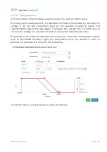
assigns the displacement factor to the relevant power, for example on basis of a two-
point characteristic curve, and converts it into a reactive power(Q) control value using
the active power P recorded by the selected measuring device at the grid connection
point.
This procedure is configured in a similar manner to the cos
ϕ
(P) procedure (cf. Section
This procedure requires a power quality analyzer that has been connected
to the data logger and configured.


