background image

4

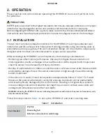
OPERATION

Table 1  Installation (continued)

Connecting

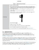
Secure and Protect Cables

NOTE:  Improperly protected cables can lead to severed cables or disconnected sensors. 
Cabling issues can be caused by many factors such as rodent damage, driving over sensor 
cables, tripping over cables, not leaving enough cable slack during installation, or poor 
sensor wiring connections. 

Install cables in conduit or plastic cladding when near the ground to avoid 

rodent damage. 

Gather and secure cables between the HYDROS 21 and the data logger to the 

mounting mast in one or more places.

Port 1

Port 2

Port 3

Port 4 

Port 5

Port 6

TEST

OK

ERROR 

(-)

(-)

(-)

(-)

(-)

(+)

(-)

(+)

(+)

(+)

(+)

(+)

Connect to Data Logger

Plug the sensor into a data logger.

Use the data logger to make sure the sensor is reading properly.

Verify that these readings are within expected ranges.

For more instructions on connecting to data loggers, refer t

Section 2.2

.

2.2  CONNECTING

The HYDROS 21 works seamlessly with METER data loggers. The HYDROS 21 can 
also be used with other data loggers, such as those from Campbell Scientific, Inc. For 
extensive directions on how to integrate the sensors into third-party loggers, refer to the 

HYDROS 21 Integrator Guide

.

HYDROS 21 sensors require an excitation voltage in the range of 3.6 to 15.0 VDC and operate 
at a 3.6-VDC level for data communication. HYDROS 21 can be integrated using DDI serial 
or SDI-12 protocol. See the 

HYDROS 21 Integrator Guide 

for details on interfacing with data 

acquisition systems.

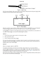
HYDROS 21 sensors come with a 3.5-mm stereo plug connector (

Figure 1

) to facilitate easy 

connection with METER loggers. HYDROS 21 sensors may be ordered with stripped and 
tinned wires to facilitate connecting to some third-party loggers (

Section 2.2.2

).

Summary of Contents for HYDROS 21 GEN 1

Page 1: ...HYDROS 21 GEN 1...

Page 2: ...tion 7 3 System 8 3 1 Specifications 8 3 2 Components 11 3 3 Theory 11 3 3 1 Water Depth 11 3 3 2 Temperature 12 3 3 3 Electrical Conductivity 12 4 Service 13 4 1 Calibration 13 4 2 Cleaning 13 4 2 1...

Page 3: ......

Page 4: ...nitoring wells or piezometers surface water monitoring and wetland monitoring The sensor cable is vented to remove the effects of barometric pressure changes The sensor also features a precision therm...

Page 5: ...ns Biofouling can affect sensor performance One way to mitigate the accumulation of microorganisms plants and algae is to wrap the sensor with a copper mesh Inspect and clean the sensor more frequentl...

Page 6: ...em grip to suspend the sensor in its final position Sensor in groundwater well Cap the well Ensure the well is able to vent to atmospheric pressure Surface Water Installation Suspend HYDROS 21 in Wate...

Page 7: ...that these readings are within expected ranges For more instructions on connecting to data loggers refer to Section 2 2 2 2 CONNECTING The HYDROS 21 works seamlessly with METER data loggers The HYDRO...

Page 8: ...te software application to configure the chosen logger port for the HYDROS 21 METER data loggers will automatically recognize HYDROS 21 sensors 3 Set the measurement interval METER data loggers measur...

Page 9: ...ne of the following two options Option 1 1 Clip off the stereo plug connector on the sensor cable 2 Strip and tin the wires 3 Wire it directly into the data logger This option has the advantage of cre...

Page 10: ...MENU button to bring up the Configuration tab NOTE If the PROCHECK does not have this option please upgrade its firmware to the latest version from the METER Legacy Handheld Devices webpage 2 Scroll...

Page 11: ...f 25 C Temperature Range 11 to 49 C Resolution 0 1 C Accuracy 1 C Water Depth Range 0 10 000 mm Resolution 1 mm Accuracy 0 5 of full scale at 20 C NOTE Depth measurement accuracy assumes no abrupt tem...

Page 12: ...le length Cable Diameter 6 mm Connector Types 3 5 mm stereo plug connector or stripped and tinned wires ELECTRICAL AND TIMING CHARACTERISTICS Supply Voltage VCC to GND Minimum 3 6 V Typical NA Maximum...

Page 13: ...1 0 mA Current Drain while asleep Minimum NA Typical 0 3 mA Maximum NA Power Up Time DDI serial Minimum NA Typical 475 ms Maximum 500 ms Power Up Time SDI 12 Minimum 300 ms Typical 475 ms Maximum 500...

Page 14: ...n resin The electronic circuitry is encapsulated in a marine grade epoxy to protect the sensor in corrosive environments Figure 4 HYDROS 21 component diagram 3 3 THEORY This section explains the theor...

Page 15: ...alts in the water and for information about dissolved solids The HYDROS 21 measures EC by applying an alternating electrical current to two electrodes measuring the current flow through those electrod...

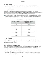
Page 16: ...ted to 25 C Table 2 HYDROS 21 calibration values Electrical Conductivity mS cm Concentration of KCl in Distilled Water g kg 100 0 0446 200 0 0930 500 0 2456 1 000 0 5120 2 000 1 0673 5 000 2 8186 10 0...

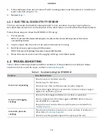
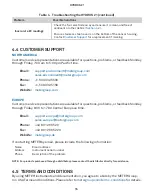
Page 17: ...roughly with tap or distilled water 4 3 TROUBLESHOOTING Table 3 lists common problems and their solutions If the problem is not listed or these solutions do not solve the issue contact Customer Suppor...

Page 18: ...509 332 5600 Fax 1 509 332 5158 Website metergroup com EUROPE Customer service representatives are available for questions problems or feedback Monday through Friday 8 00 to 17 00 Central European tim...

Page 19: ...16 REFERENCES REFERENCES Sprecher S W 2008 Installing Monitoring Wells in Soils Version 1 0 National Soil Survey Center Natural Resources Conservation Service USDA Lincoln NE...

Page 20: ...customer support 15 E electrical conductivity 8 12 email address 15 F fax number 15 I installation 2 3 groundwater well 2 3 tools required 2 water body 3 P phone number 15 R range 8 references 16 S s...

Page 21: ...Court Pullman WA 99163 T 1 509 332 2756 F 1 509 332 5158 E info metergroup com W metergroup com METER Group AG Mettlacher Stra e 8 81379 M nchen T 49 89 1266520 F 49 89 12665220 E info europe metergr...

Page 22: ......

Reviews: