5
TEROS 06
TEROS 06 sensors require an excitation voltage in the range of 3.9 to 28.0 VDC and operate
at a 3.3-VDC level for data communication. TEROS 06 can be integrated using DDI serial,
SDI-12 protocol, Modbus RTU protocol, or tensioLINK protocol. See the
TEROS 06 Integrator
Guide
for details on interfacing with data acquisition systems.
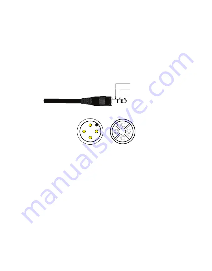
TEROS 06 sensors come with either a 3.5-mm stereo plug connector (
to facilitate easy connection with METER loggers or with a 4-pin M12 connector
(
) to facilitate connecting to some third-party loggers (
).
The TEROS 06 comes standard with a 4.5-m cable. In some instances, the cable can be
extended beyond 75 m by the user, but this is discouraged for a variety of reasons. Please
contact
for more details before extending or splicing cables.
Ground
Digital communication
Power
Figure 2 3.5-mm stereo plug connector wiring used with METER loggers
1
1
2
2
3
3
4
4
Male plug on
sensor cable
Female plug on
connecting cable
Figure 3 4-pin M12 plug connector used with non-METER loggers
2.3.1 CONNECT TO METER DATA LOGGER
The TEROS 06 works most efficiently with METER ZENTRA series data loggers. Check the
METER download webpage (
) for the most recent data logger
firmware. Logger configuration may be done using either ZENTRA Utility (desktop and mobile
application) or ZENTRA Cloud (web-based application for cell-enabled data loggers).
METER recommends using a standard stereo plug connector with a METER ZENTRA series
data logger using SDI-12 communications protocol.
1. Plug the 3.5-mm stereo plug connector into one of the sensor ports on the logger.
2. Use the appropriate software application to configure the chosen logger port for the
TEROS 06. METER data loggers will automatically recognize TEROS 06 sensors.
3. Set the measurement interval.
METER data loggers measure the TEROS 06 every minute and return the average of the
1-min data across the chosen measurement interval.
Summary of Contents for TEROS 06
Page 2: ......


