background image

11

CUSTOMER SUPPORT

Customer service representatives are available for questions, problems, or feedback Monday through Friday, 
8 am–5 pm Pacific time. 

Email:

 support.environment@metergroup.com

 sales.environment@metergroup.com

Phone:

 +1.509.332.5600

Fax:

 +1.509.332.5158

Website:


www.metergroup.com

If contacting METER by email, please include the following information:

Name

Address

Phone number

Email address

Instrument serial number

Description of problem

NOTE:  For TEROS 21 sensors purchased through a distributor, please contact the distributor directly for assistance.

REVISION HISTORY

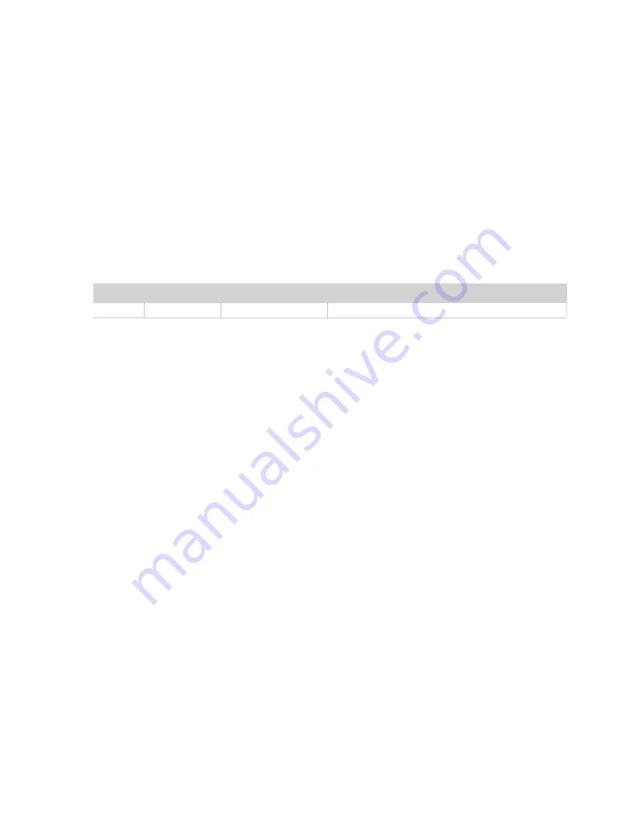
The following table lists document revisions.

Revision

Date

Compatible Firmware Description

00

11.10.2017

3.89

Initial release


Summary of Contents for TEROS 21

Page 1: ...tential sensor can be packed into a hole plugged into a data logger and left to log water potential data While the TEROS 21 sensor does not have the accuracy of tensiometers its extended range makes this sensor ideal for measuring the water potential in natural systems or other drier systems where cavitation of tensiometers is a concern The added temperature measurements can be used to determine a...

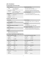
Page 2: ...erating Temperature 40 to 60 C 0 to 100 RH No water potential measurement 0 C NOTE Sensors may be used at higher temperatures under certain conditions contact Customer Support for assistance Power Requirements 3 6 to 15 VDC 0 03 mA quiescent 10 mA maximum during 150 ms measurement Supply Voltage VCC to GND Minimum 3 6 VDC Typical Maximum 15 0 VDC Digital Input Voltage logic high Minimum 2 8 V Typi...

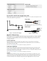
Page 3: ...ty logger Visit https www metergroup com for articles containing more information POWER AND GROUNDING Ensure there is sufficient power to simultaneously support the maximum sensor current drain for all the sensors on the bus The sensor protection circuitry may be insufficient if the data logger is improperly powered or grounded Refer to the data logger s installation instructions Improper groundin...

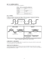
Page 4: ...or require some type of interface hardware to be compatible with the serial port found on most computers or USB to serial adapters There are several SDI 12 interface adapters available in the marketplace however METER has not tested any of these interfaces and cannot make a recommendation as to which adapters work with METER sensors METER data loggers and the ProCheck hand held device can operate ...

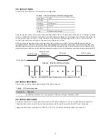
Page 5: ...transmission of the character 1 0x31 Break at least 12 ms Marking at least 8 33 ms Marking at least 8 33 ms Command Response SENSOR DATA LOGGER Maximum time Sensor must respond within 15 ms Maximum time is dependent upon the amount of data returned for the command sent Figure 5 Example data logger and sensor communication COMMON SDI 12 COMMANDS This section includes tables of common SDI 12 command...

Page 6: ...dresses are alphanumeric i e a z A Z and 0 9 An example output from a METER sensor is shown in Example 2 where the command is in bold and the response follows the command Example 2 1A0 0 Parameter Fixed Character Length Description 1A0 4 Data logger command Request to the sensor to change its address from 1 to a new address of 0 0 1 New sensor address For all subsequent commands this new address w...

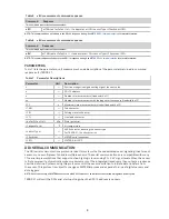
Page 7: ... specified amount of time detailed in the C command response and then use D commands to read its response prior to communicating with another sensor Please refer to Table 3 for an explanation of the command sequence and see Table 7 for an explanation of response parameters Table 3 aC measurement command sequence Command Response This command reports average values when relevant aC attnn aD0 a wate...

Page 8: ...ake fixed width of 3 TAB Tab character CR Carriage return character LF Line feed character waterPotential kPa Water potential temperature C Air temperature sensorType ASCII character denoting the sensor type For TEROS 21 the character is k Checksum METER serial checksum CRC METER 6 bit CRC DDI SERIAL COMMUNICATION The DDI serial communications protocol is ideal for systems that have dedicated seri...

Page 9: ...nd a measurement Then the sensor may take some additional measurements before starting to clock out the first data byte starting with a typical start bit low Once the first start bit is sent typical serial timing is valid however the signal transitions before this point are not serial signaling and may be misinterpreted by the UART SDI 12 ready DDI serial Measurement duration Up to 100 ms Power ap...

Page 10: ...m character CRC6 checksum example input is TAB 34 8 22 3 CR k and the resulting checksum output is l lowercase L uint8_t CRC6_Offset uint8_t buffer uint16_t bytes uint16_t byte uint8_t bit uint8_t crc 0xfc Set upper 6 bits to 1 s Loop through all the bytes in the buffer for byte 0 byte bytes byte Get the next byte in the buffer and XOR it with the crc crc buffer byte Loop through all the bits in t...

Page 11: ...9 332 5158 Website www metergroup com If contacting METER by email please include the following information Name Address Phone number Email address Instrument serial number Description of problem NOTE For TEROS 21 sensors purchased through a distributor please contact the distributor directly for assistance REVISION HISTORY The following table lists document revisions Revision Date Compatible Firm...

Reviews: