4.2.2004
Rev. 1.0
Installation
20
In order to avoid the risk of tearing the power cord, lock it in place using the cable gland
(item 32 in Fig. 8) fitted on the appliance.
The length of the ground (earth) cable should be such as to allow it to suffer any possible
mechanical stress the live leads.
5.8.4 Equipotential bonding terminal
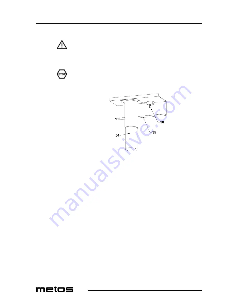
The equipment must be connected to an equipotential bonding system. To that end, there
is a connection terminal marked "equipotential" (see Fig. 9) found on the lower left side
of the appliance, near the various supply connections.
Fig. 9
34.
Front left foot
35.
Frame
36.
Equipotential bonding terminal
5.9 Staff training
Inform all personnel assigned to operate the appliance on how to use it by referring to the
user’s manual and hand them out the manual as well.
Summary of Contents for 72/02TVTC
Page 2: ......
Page 4: ...4 2 2004 Rev 1 0...
Page 10: ...4 2 2004 Rev 1 0 Safety 4...
Page 14: ...4 2 2004 Rev 1 0 Functional description 8...
Page 20: ...4 2 2004 Rev 1 0 Operating instructions 14...
Page 28: ...4 2 2004 Rev 1 0 Installation 22...
Page 32: ...SC00430 Wiring diagram 74 02VTCE 3 N PE 400V 50 60 Hz...
Page 34: ...SC00431 Wiring diagram 74 02VTC 74 02TVTC 3 N PE 400V 50 60 Hz...
Page 36: ...SC00432 Wiring diagram 72 02VTC 72 02TVTC 3 N PE 400V 50 60 Hz...
Page 43: ...4 2 2004 Rev 1 0 Technical specifications 47...
Page 44: ...4 2 2004 Rev 1 0 Technical specifications 48...
Page 46: ...4 2 2004 Rev 1 0 Technical specifications 50...
Page 48: ......
Page 49: ......
Page 50: ......


