background image

DOMITOR DM/DB

GB - 16 

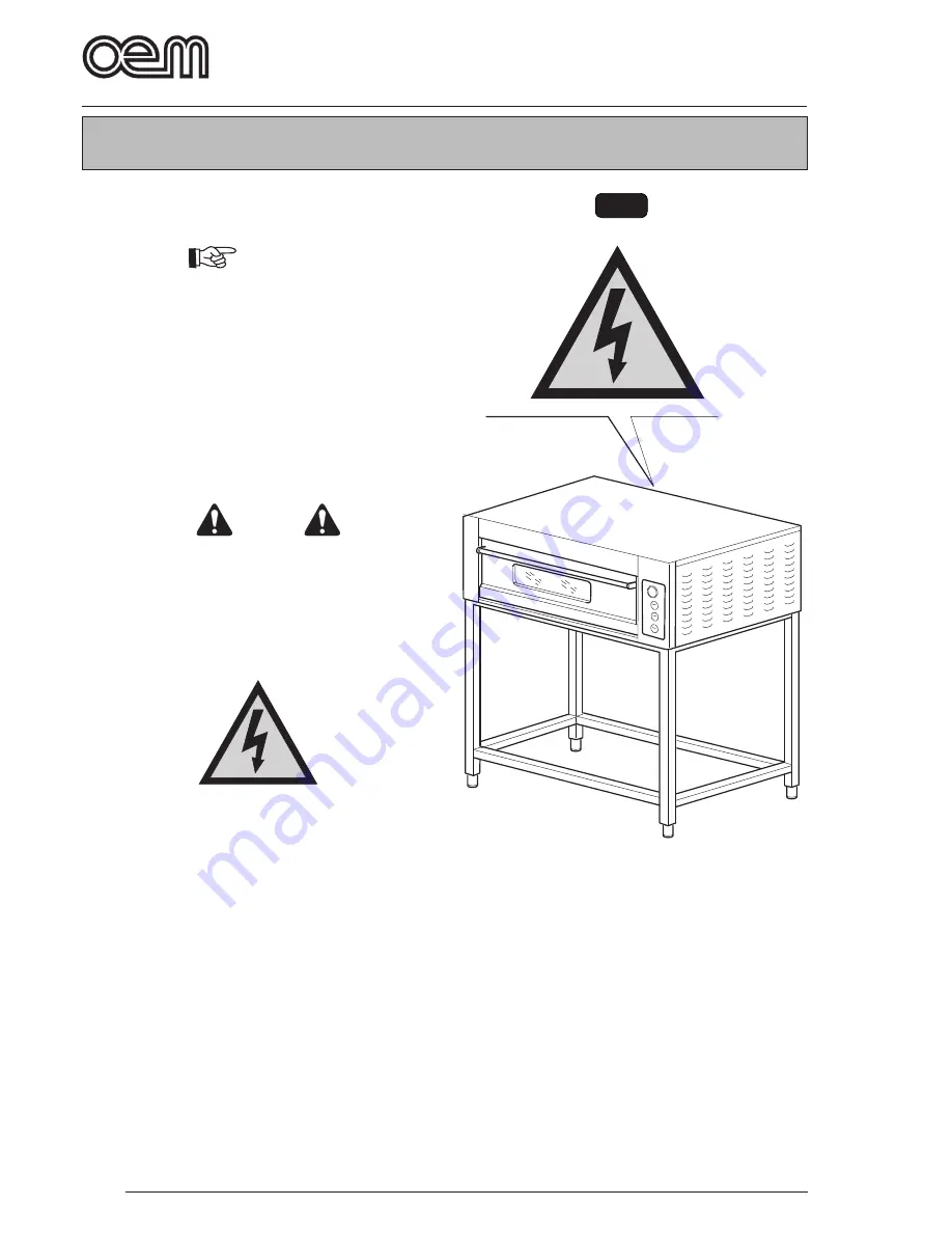
Safety devices

FIG. 1

4.1 - TYPE OF USE AND CONTRAINDICA-

TIONS 

 IMPORTANT

DOMITOR DM/DB ovens are professional machines 
suitable for baking pizza and similar products.
The various models shall only be used to process 
as above; in case of any other use, manufacturer 
disclaims all responsibility for accidents to persons 
or objects and customer will be debarred from a 
possible guarantee right.

4.2 - SAFETY PLATES (Fig. 1)

The warning plates with explanatory symbols are to 
be found in all those areas that may be dangerous for 
operators or engineers.

 DANGER 

On the oven, there are plates reporting safety 
instructions which shall absolutely be followed 
by any oven user. Manufacturer disclaims all 
responsibility in case of accidents to persons 
or objects arising from a non-fulfi lment of such 
instructions.

Danger: machine under voltage 

•  Do not work with the machine under voltage.

Chapter 4

Summary of Contents for DOMITOR

Page 1: ...Installation and Operation Manual PIZZA OVEN DOMITOR...

Page 2: ......

Page 3: ...BAKING Page GB 20 5 4 SELF CLEANING CYCLE Page GB 20 5 5 CUTTING OFF Page GB 20 5 6 MALFUCTIONING CAUSE AND CURE Page GB 21 5 7 SAFETY THERMOSTAT RECHARGE Page GB 21 CHAPTER 6 Chapter for the technici...

Page 4: ......

Page 5: ...only suitable tools should be used in accordance with the local safety regulations Do not tamper the electric and pneumatic plant or any other mechanism for any reason The oven shall not be left ungua...

Page 6: ...lates shall be read understood and observed To identify the safety messages included in this bo oklet following symbols have been used DANGER This symbol is used in the safety messages con tained in t...

Page 7: ...nditions c Flue prearrangement It is necessary to prearrange a vapour flue whose features shall be in compliance with the rules being in force in the Country the oven shall be installed in b Neutral w...

Page 8: ...50 950 950 730 170 900 950 437 900 950 1230S 630 930 150 950 1300 730 170 1250 950 437 1250 950 1230L 930 630 150 1250 950 730 170 900 1250 437 900 1250 Mod Inside size Outside size Support L P A L1 P...

Page 9: ...3 5x4 400 C 830 8 8 230V 3 4x4 400 C 10 80 400V 3 5x4 400 C 1230S 15 6 230V 3 4x4 400 C 10 80 1230L 400V 3 5x4 400 C Model Power Electric Cable Max Relative kW max connection section temperature humid...

Page 10: ...2 2200 8 8 EE28200 DB1230S 2 Camere 6 1300 2 Camere 6 1300 15 6 EE24600 DB1230L 2 Camere 6 1300 2 Camere 6 1300 15 6 EE24700 Model Ceiling Bedplate Max Code resistance resistance Power N W CAD N W CA...

Page 11: ...osition the box use suitable lifting systems according to the weight of the machine The box should be lifted by using a crane or a hoist with appropriate belts or by means of a lift track by inserting...

Page 12: ...the components are assembled 2 4 UNPACKING Fig 3 To remove the oven from its packing proceed as follows Cut the straps 1 that tie up the carton Open the carton 2 by removing the metallic clips Remove...

Page 13: ...ICATION OF THE COMPONENTS Fig 4 1 Hood 2 Oven 1 3 Oven 2 4 Support 5 Wheels Optional 6 Control board 7 Data plate 2 6 OVEN IDENTIFICATION Fig 4 Oven serial number and identification data are reported...

Page 14: ...h a hook 4 of a crane or a tackle ATTENTION To hoist the machine do not use steel belts as they may damage the outside body 3 2 ASSEMBLING OF THE COMPONENTS IMPORTANT Regarding the assembling of the s...

Page 15: ...cond one and fixed as above Hood assembling Fig 5 The hood 10 shall be positioned on the last oven and fixed by the four existing screws 11 Chimney assembling Fig 5 Unpack the chimney 12 and place it...

Page 16: ...ANGER Before connecting the machine with the electric line make sure that the DISCONNECTING SWITCH is disconnected line not energized 3 3 a Electric oven connection To reach the electric oven part rem...

Page 17: ...mable flooring shall be utilized to install the oven on it The oven shall be positioned on the final area following the indications reported in figure 8 because they indicate the minimum distances req...

Page 18: ...customer will be debarred from a possible guarantee right 4 2 SAFETY PLATES Fig 1 The warning plates with explanatory symbols are to be found in all those areas that may be dangerous for operators or...

Page 19: ...king chamber 4 4 USER S AREAS Fig 3 During the oven functioning user is in front of it in order to be able to easily insert and remove the pizza through the door 1 see Fig 3 O position To carry out ma...

Page 20: ...to do it please refer to the graduated scale 3 Bedplate resistance lamp Lights up when the bedplate resistances are on it goes out when the oven reaches the set temperatu re 4 Crown plate temperature...

Page 21: ...since the oven temperature would in such a case be 50 60 C higher than the set one and pizzas will burn 5 2 a Oven starting Fig 2 Turn the selector switch 1 onto ON the lamp 2 as well as the lamp 3 a...

Page 22: ...he pizza is baked open the oven access door and remove the baked pizza 5 4 SELF CLEANING CYCLE Fig 3 The self cleaning cycle shall be carried out after using the oven for several hours at the end of e...

Page 23: ...ke sure the electric oven connection has properly been carried out Contact manufacturer s technical service DANGER For all other troubles do not hesitate to contact manufacturer s technical service 5...

Page 24: ...ASE OF NEED Some operations to be carried out in case of need for instance the replacement of broken or worn components 6 1 b Ordinary maintenance 6 1 b a Outer cleaning to be carried out every day AT...

Page 25: ...ndle the refractory surface DO NOT wash with water DO NOT wash in a dish washer DO NOT utilize detergents to clean the refractory surfaces only use a wet cloth 6 1 c b Every 2 years Contact manufactur...

Page 26: ...ser shall place himself at the rear side of the oven and remove the rear panel 1 with chimney loosening the relevant screws Remove the oven covering mineral wool 2 loosen the resistance fixing screws...

Page 27: ...tech nicians Remove the right hand panel 1 by unscrewing the relevant screws Remove the control board 2 by unscrewing the relevant screws Release the spring 3 and replace it Insert the spring 3 in th...

Page 28: ...7 6 1 d e Door pane replacement Fig 7 DANGER This operation shall be carried out by skilled tech nicians Open the door 1 and remove the inner panel 2 loosening the relevant screws 3 Replace the pane...

Page 29: ...waste it must be disposed of according to the special EU directive for the recycling of electric and electronic equipment The electrical equipment is marked with a pictogram of a garbage can inside a...

Page 30: ...diagram GB 28 2 6 4 1 3 5 KM A1 A2 L1 L2 L3 N PE BN RD GY YW GN BU BN BN BN BN BN BN BN BN BN BU BU BN BU GY RD RD GY WE WE BK BU BU ST1 ST2 ST3 R1 R2 Q KM EL1 EL2 230V 40W EL3 EL4 WIRING DIAGRAM DM...

Page 31: ...agram GB 29 2 6 4 1 3 5 KM A1 A2 L1 L2 L3 N PE BN RD GY YW GN BU BN BN BN BN BN BN BN BN BN BU BU BN BU GY RD RD GY WE WE BK BU BU ST1 ST2 ST3 R1 R2 Q KM EL1 EL2 230V 40W EL3 EL4 WIRING DIAGRAM DM 430...

Page 32: ...diagram GB 30 2 6 4 1 3 5 KM A1 A2 L1 L2 L3 N PE BN RD GY YW GN BU BN BN BN BN BN BN BN BN BN BU BU BN BU GY RD RD GY WE WE BK BU BU ST1 ST2 ST3 R1 R2 Q KM EL1 EL2 230V 40W EL3 EL4 WIRING DIAGRAM DM...

Page 33: ...M 2 A 1 A 2 L 1 L 2 L 3 N P E V T B U B U B U B U W E V T B U V T V T R D G Y B K W E W E W E R D G N B K R D G Y B K B N B N B N R D G N B K W E W E B U V T S T 1 S T 2 S T 3 E L 3 E L 1 E L 2 E L 4...

Page 34: ...3 5 KM2 L1 L2 L3 N PE RD GY BK WE WE WE RD GN BK RD GY BK BN BN BN RD GN BK R1 R2 R3 R4 R6 R5 Q1 KM1 A1 A2 KM2 A1 A2 VT BU BU BU BU WE VT BU VT VT WE WE VT ST1 ST2 ST3 EL3 EL1 EL2 EL4 230V 40W WE BU...

Page 35: ...BN BN BN BN BN BN BU BU BN BU GY RD RD GY WE WE BK BU BU ST1 ST2 ST3 R1 R2 Q1 KM1 EL1 EL2 230V 40W 2 6 4 1 3 5 KM2 A1 A2 BN RD GY BU BN BN BN BN BN BN BN BN BN BU BU BN BU GY RD RD GY WE WE BK BU BU...

Page 36: ...BN BN BN BN BN BN BU BU BN BU GY RD RD GY WE WE BK BU BU ST1 ST2 ST3 R1 R2 Q1 KM1 EL1 EL2 230V 40W 2 6 4 1 3 5 KM2 A1 A2 BN RD GY BU BN BN BN BN BN BN BN BN BN BU BU BN BU GY RD RD GY WE WE BK BU BU...

Page 37: ...BU BU KM1 A1 A2 KM2 A1 A2 BU BU BU BU WE VT VT VT WE WE ST2 ST3 EL3 EL1 EL2 EL4 230V 40W WE BU BU 2 6 4 1 3 5 KM1 2 6 4 1 3 5 KM2 RD GY BK WE WE WE RD GN BK RD GY BK BN BN BN RD GN BK R1 R2 R3 R4 R6 R...

Page 38: ...3 R4 R6 R5 2 6 4 1 3 5 KM3 2 6 4 1 3 5 KM4 RD GY BK WE WE WE RD GN BK RD GY BK BN BN BN RD GN BK BU R7 R8 R9 R10 R12 R11 Q2 VT VT ST4 BU KM1 A1 A2 KM2 A1 A2 BU BU BU BU WE VT VT VT WE WE ST2 ST3 EL3 E...

Page 39: ...istance R2 Bottom resistance ST1 Safety thermostat ST2 Upper thermostat ST3 Bottom thermostat OVEN CAPTION 630 635 930 935 V400 230 EL1 Led ON OFF EL2 Lamp EL3 Upper thermostat led globe EL4 Bottom pl...

Page 40: ...Contactor Q1 Main switch R1 Upper resistance R2 Bottom resistance ST1 Safety thermostat ST2 Upper thermostat ST3 Bottom thermostat BOTTOM ROOM EL5 Led ON OFF EL6 Lamp EL7 Upper thermostat led globe E...

Page 41: ...R6 Bottom resistance ST1 Safety thermostat ST2 Upper thermostat ST3 Bottom thermostat BOTTOM ROOM EL5 Led ON OFF EL6 Lamp EL7 Upper thermostat led globe EL8 Bottom plane thermostat led globe F2 Antij...

Page 42: ......

Reviews: