19.01.2015
Metos Induction range Dominator
4
Do not place any metal objects, such as kitchen utensils, cutlery, aluminium foil or plastic vessels upon
the glass-ceramic hob.
Items such as rings, watches, bracelets, etc. worn by the user could become hot when in close proximity
to cooking zone. Do not place credit cards, etc. on glass-ceramic top as data could be wiped.
Never leave induction hob unsupervised when in use.
The glass-ceramic top must NOT be used for storage. Do not place cloths etc. over appliance rear.
This may impede flue outlet and cause overheating of appliance.
3. Operation
3.1. Induction hob
Use of correct pan type is essential for proper operation.
Suitable pans are those made with ferrous materials, ie, ferrous stainless steel, steel. Use a magnet to
check, if magnet sticks to base, the pan should be OK to use.
Warning – this only tests function – not quality.
Poor quality will reduce efficiency and performance.
Always place pans centrally upon cooking zone for optimum performance and safety.
Optimum pan diameter is 270 mm. Do not use pans of less than 120 mm diameter.
If a pan base is damaged or warped, ie concave or convex, discontinue use as this will seriously affect
performance.
Each cooking zone is controlled by a marked, variable
control from 1 (lowest) to 10 (highest).
The ideal setting for simmering or fast boiling pans of
varying size will quickly be established through experi-
ence.
Each control has a green LED indicator. When
a cooking zone is switched on, the LED indicator will
light and stay lit during heating/cooking.
If pan is removed from zone, LED will flash approxi-
mately once per second to indicate cooking zone is still
active, awaiting detection of a pan.
After use, switch off cooking zones by returning control
to OFF position. DO NOT rely on pan detector or safety
features to isolate cooking zone.
Note: Positioning lines available for centralising pot(s).
It is important that pots are magnetic or
induction- approved.
A guide to the correct use of pans and cooking zones is provided on
Pages 4 and 5.
3
Each cooking zone is controlled by a marked, variable
control from 1 (lowest) to 10 (highest). The ideal setting
for simmering or fast boiling pans of varying size will
quickly be established through experience.
Each control has a green LED indicator. When a cooking
zone is switched on, the LED indicator will light and stay
lit during heating/cooking. If pan is removed from zone,
LED will flash approximately once per second to indicate
cooking zone is still active, awaiting detection of a pan.
After use, switch off cooking zones by returning
control to OFF position. DO NOT rely on pan detector
or safety features to isolate cooking zone.
Note: Positioning lines available for centralising
pot(s).
It is important that pots are magnetic or induction-
approved.
A guide to the correct use of pans and cooking zones is
provided on Pages 4 and 5.
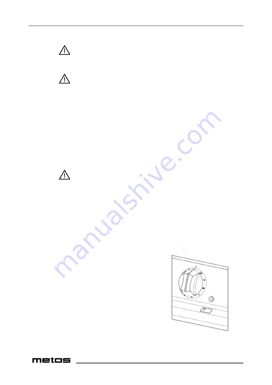
control knob
LED indicator (green)
Figure 2 - Hob zone control
OVEN
The oven is controlled by a thermostat.
An amber neon, when lit, indicates that current is
being supplied to the elements. This will go out
when oven has reached selected temperature.
Grid Shelves
Two oven shelves are supplied. Five shelf
positions are available. If two shelves are used
at once, they should be spaced at least two
runners apart, e.g. 1
–
3, 3
–
5 etc.
Tray Size
The oven accommodates 1 x 1 gastronorm trays
(530 x 325mm) or other types
up to 530 x 500mm.
Trays and dishes should always be
located centrally on the shelves.
Pre-Heating Time
control knob
oven light switch
temperature
indicator (amber)
mains on neon (red)
Figure 3 - Oven control
Allow at least 45 mins from switching on from cold,
irrespective of temperature setting.
Insert food items quickly and close the doors firmly.
Oven Light
Push and hold switch to view items while cooking.


