background image

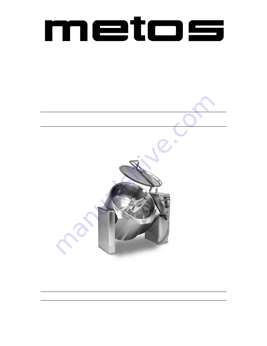
COMBI-KETTLE

PROVENO S

TYPE: 40, 60, 80, 100, 150, 200, 300 

CHILL LINE

Installation and Operation Manual

S/N: 10910511010010

Valid from:  01.11.2005

Rev.: 1.5

Chill Pro S SCE  4222106, 4222107, 4222108, 4222109, 4222110
Chill Pro S DCE  4222111, 4222112, 4222121, 4222122, 4222123

Summary of Contents for PROVENO S 100

Page 1: ...0 60 80 100 150 200 300 CHILL LINE Installation and Operation Manual S N 10910511010010 Valid from 01 11 2005 Rev 1 5 Chill Pro S SCE 4222106 4222107 4222108 4222109 4222110 Chill Pro S DCE 4222111 42...

Page 2: ......

Page 3: ...pliance The instructions and hints in this manual will give you a quick and easy start and you will soon note how nice it is to use the Metos equipment All rights are reserved for technical changes Yo...

Page 4: ...2 11 2005 Rev 1 5...

Page 5: ...prohibitions dangerous methods and procedures 8 3 Functional description 9 3 1 Intended use of the appliance 9 3 1 1 Use for other purposes 9 3 2 Construction 9 3 3 Operating principle 9 3 4 Operation...

Page 6: ...ling the combi kettle on the frame 35 5 3 Electrical connections 39 5 4 Water connections 42 5 4 1 Flo Ice connections C4 option 42 5 4 2 Water connection and quality requirements 43 5 4 3 Extreme wat...

Page 7: ...2 11 2005 Rev...

Page 8: ...2 11 2005 Rev...

Page 9: ...ed by the manufacturer and using original spare parts Not complying with the above may put the safety of the appliance in danger 1 1 Symbols used in the manual This symbol informs about a situation wh...

Page 10: ...kettle is a pressurized vessel with a maximum operating pressure of 1 bar or 0 5 bar for certain markets Overpressure is prevented by means of both me chanical safety valve pressure switch and electr...

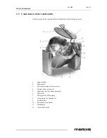
Page 11: ...strated in the following pictures 1 Support pillar 2 Safety block 3 Mixer and mixing tool accessory 4 Strainer plate accessory 5 Emptying valve for steam generator 6 Safety lid 7 Safety grid for fill...

Page 12: ...tructions 4 Lid 1 Safety lid 2 Lifting arm 3 Locking lever of the lid 4 Safety grid for fill opening 5 Safety switch 6 Cover for fill opening Control panel and mains switch 1 Control panel 2 Emergency...

Page 13: ...ng and mixer 5 ON OFF switch 6 Error message lights 7 Stop to stop the mixer 8 Starting time 9 Displays for timer water fill EasyRun programming and cooling 10 Function time 11 Automatic water fill 12...

Page 14: ...ool after cooking Use protective gloves Do not open the bottom valve or the emptying valve of the steam generator when the kettle is hot pressurized Always make sure that the mixing speed is appropria...

Page 15: ...The mixing tool is easier to position and remove from the kettle when the kettle is in a tilted position ergonomics Protect yourself in an appropriate way when cleaning the kettle follow safety and h...

Page 16: ...t to the right In case the reason for using the emergency stop switch is a serious malfunction jeopardizing safety at work contact your Metos service provider immediately 1 Emergency stop button 2 Mai...

Page 17: ...caused by misuse or use for other purposes than stated above 3 2 Construction The construction of the kettle is of stainless steel throughout AISI 304 The inner bottom and jacket are of acid proof st...

Page 18: ...ntral dial Turning clockwise to the right increases and turn ing anticlockwise to the left decreases the value being selected If a button is fitted with an indicator light it shows if a function is on...

Page 19: ...ting and mixer 5 ON OFF switch 6 Error message lights 7 Stop to stop the mixer 8 Starting time 9 Displays for timer water fill EasyRun programming and cooling 10 Function time 11 Automatic water fill...

Page 20: ...iance does not get water Blinking SEt in the cooling function reminds you to start the mixer to make cool ing more efficient 3 4 2 Error message lights There are two red indicator lights on the contro...

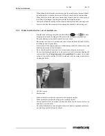
Page 21: ...of the mixer axle with the handle turned in a horizontal position Se cure fixing by trying to lift the tool out of the kettle by the upper blade Quarterly check safety valve It is the responsibility o...

Page 22: ...ettle _________________ Serial No __________________ Taken into use date __________________ Quarterly safety valve check performed Yearly maintenance performed Descaling performed Date By Remarks Date...

Page 23: ...button for a long time approx 2 seconds 4 2 2 Tilting the kettle It is not possible to tilt the kettle when the lid is closed In case you try to tilt the kettle with the lid in a closed position a bl...

Page 24: ...pers are not needed when preparing large quantities of mashed potatoes or when kneading dough Use scrapers in all other cooking modes to increase the efficiency of heat transfer and to help the cleani...

Page 25: ...ooking Switch on the appliance On appears on the temperature display Press the temperature button once Select temperature with the central dial When the temperature starts to blink on the display you...

Page 26: ...ired 4 2 6 Stopping the cooking Press the temperature button for a long time approx 2 seconds The heating goes off when On appears on the display 4 2 7 Mixing functions Starting the mixer manual mixin...

Page 27: ...e mixing function Message 15 appears on the mixing display Select the desired mixing program P1 P6 Start the mixing program The display shows the number and phase of the program in operation e g P2 2...

Page 28: ...the water supply closing valve is open Automatic water fill Press once Select the amount to be filled Start filling by pressing once again The selected amount of cold water flows automatically into t...

Page 29: ...nue holding the button down until Yr blinks on the timer display and two last digits of the year illuminate Release the buttons If needed select a new year within 3 seconds After the year is locked Mo...

Page 30: ...ess and keep pressed for about 2 seconds In case the starting time has not yet been reached the starting time has to be deactivated by pressing the starting time button for about two seconds Activatin...

Page 31: ...conds i e the YeS selection is not made the cool ing function is cancelled If you however want to start cooling activate the function by starting from the beginning Changing the target temperature dur...

Page 32: ...ght position or the power is connected After the emptying time the kettle is ready for cooking On is displayed 4 2 11 EasyRun programming The following functions are possible when a set program is in...

Page 33: ...mming by pressing for about 2 seconds Select the desired setting values by first pressing the button of the appropriate program and by setting the desired value with the central dial Activate a new pr...

Page 34: ...green indicator light on the operation time button is blinking in case of several power failures their durations are summed up 4 2 13 Self control HACCP option A separate instruction manual is availa...

Page 35: ...Tools recommended for cleaning special detergents for stainless steel nylon brush soft rubbing sponges non abrasive steel wool other materials intended for stainless steel that do not scratch the surf...

Page 36: ...the mixer to make soaking more ef ficient mixing slowly during soaking Cleaning procedures Switch the appliance off Cool down the kettle with cold water Scrape loose dirt with a plastic scraper access...

Page 37: ...he guiding pin lines up with the groove of the lifting arm 1 Solid lid 2 Lifting arm 3 Guiding pin 4 Locking lever of the lid 5 Safety grid for lid opening 6 Cover for fill opening Press the lid arm a...

Page 38: ...p on the steam sys tem depends on the use of the kettle and the hardness of local water Contact the Metos service for recommendations on preventative maintenance service to be performed No parts of th...

Page 39: ...must be emptied to avoid damage caused by freezing The kettle s pipes and solenoid valve bodies must be emptied at the same time 5 1 2 Possible interference from the surroundings to the surroundings...

Page 40: ...is fixed to the floor If the kettle falls down this may cause injury to peo ple or damage to property 5 1 5 Disposal of the package In connection with unpacking all packing material must be sorted and...

Page 41: ...is 30 mm above the finished floor surface The junc tion of the installation frame and floor is filled with flooring material or silicone mastic To achieve the best result regarding tightness the inst...

Page 42: ...shers or other small spacers are not allowed The fixing bolts for the surface installation must be chosen according to the floor con struction A type recommended is a UKA M10x150 chemical bolt which s...

Page 43: ...the support pillar 1 on the installation frame 2 and adjust it by means of the adjusting bolts 3 located on the corners to a horizontal position and to a height of 900 mm measured from the top of the...

Page 44: ...trolley do not hit the parts protrud ing from the kettle bottom i e the mixing motor cover box Proveno 40 60 80 100 as well as the drain and discharge pipes Furthermore it is recommended to place e g...

Page 45: ...pports located at the front and rear edge of the control pillar slightly above the bearings When pushing the support through the control pillar be careful not to damage the cables and water pipes Befo...

Page 46: ...with the support pillar When the control pillar 1 is in position it is fixed to the installation frame 2 with four fixing bolts 4 Check that the space between the kettle section and the support and co...

Page 47: ...stallation of the first kettle on the support pillar 5 3 Electrical connections The electrical connections of the Proveno combi kettle can only be carried out by a qual ified electrician having the ne...

Page 48: ...the plate being detached entirely but you can move the plate a little aside 4 Upper side plate 5 Screw Loosen the screws 5 located on the upper and lower corners of the upper side plates 4 Turn the l...

Page 49: ...r that check phase order to make sure that the mixer and tilting motors rotate in the correct direction Close the lid and safety grid of the combi kettle but do not put the cover of the safety grid on...

Page 50: ...losing valve and a non return valve not included in delivery The sizes of water connection points are as follows Cold water connection with R1 2 inner thread supply with min 15 mm inlet pipe Hot water...

Page 51: ...ess than 60 mg l Maximum chlorine concentration allowed is less than 0 2 mg l The pH value of the water should be between 6 5 and 9 5 Unit damages caused by chloride chlorine or pH values exceeding th...

Page 52: ...ood must be installed above the kettle because plenty of steam is released when the kettle lid is opened When dimensioning the ventilation hood the space requirement for opening the lid must be taken...

Page 53: ...its cooking po sition is tilted too much backwards turn the limit switch plate 1 slightly upwards Tighten the locking nut 5 slightly after adjustment press the tilting reverse button until the kettle...

Page 54: ...the safety valve le ver When the steam is discharging sound pressure gauge reading reduces allow the lever to return to the lower position Beware of hot steam discharging from the safety valve 5 10 A...

Page 55: ...h a timer option No functions are allowed to be in operation The customer parameter setting mode can be accessed as follows Simultaneously press the temperature and the tilting reverse buttons for 3 s...

Page 56: ...and deselection of the short pull back of the tilting done after releasing the tilting Temperature Fbon FboF Pull back ON Pull back OFF Fbon Pr21 Selection and deselection of the buzzer signal used wh...

Page 57: ...2 11 2005 Rev 1 5 Adjustment instructions 49 Pr14 added 27 5 2002 Or65 Pr15 added 27 5 2003 Or71 Pr16 added 3 6 2003 Or71 Pr41 added 15 9 2003 Or73 Pr42 added 15 9 2003 Or73...

Page 58: ...osition after tilting the temperature display shows a PoS signal Press the tilting reverse button until the kettle is totally horizontal and the temperature display shows an On signal Electric kettle...

Page 59: ...the amount and restart Other technical fault Contact qualified technical personnel Timing of the kettle not possible The kettle is not returned to an upright position after tilting the temperature di...

Page 60: ...or the unit in ques tion what is the type and model of the unit what is the serial number of the unit and the date the unit has been installed a short description of the fault what function is not wor...

Page 61: ...11 2005 Rev 1 5 Technical specifications 53 8 Technical specifications Connection diagram S00123 B3 Installation drawing L00115 B3 Text part ChillPlus L00114 A4 Steam supply recommendations 000030 A4...

Page 62: ...Connection diagram S00123 B3...

Page 63: ...Installation drawing L00115 B3...

Page 64: ...Text part ChillPlus L00114 A4...

Page 65: ...Steam supply recommendations 000030 A4...

Page 66: ...shell to floor 80 100 465 mm Tilting height from outer shell to floor 150 200 460 mm Tilting height from outer shell to floor 300 450 mm Maximum height of cover 40 60 1800 mm Maximum height of cover...

Page 67: ...of mixing tool 150 M MC4P 4 7 kg Weight of mixing tool 200 M MC4P 5 5 kg Weight of mixing tool 300 M MC4P 6 5 kg Number of scrapers 60 80 M MC4P 2 Number of scrapers 100 150 M MC4P 3 Number of scraper...

Page 68: ......

Reviews: