MI 3122 Smartec Z Line-Loop / RCD
Testing RCD
24
5 Measurements
5.1 Testing RCDs
Various test and measurements are required for verification of RCD(s) in RCD protected
installations. Measurements are based on the EN 61557-6 standard.
The following measurements and tests (sub-functions) can be performed:
Contact voltage,
Trip-out time,
Trip-out current,
RCD autotest.
See chapter
4.1 Function selection
for instructions on
key functionality.
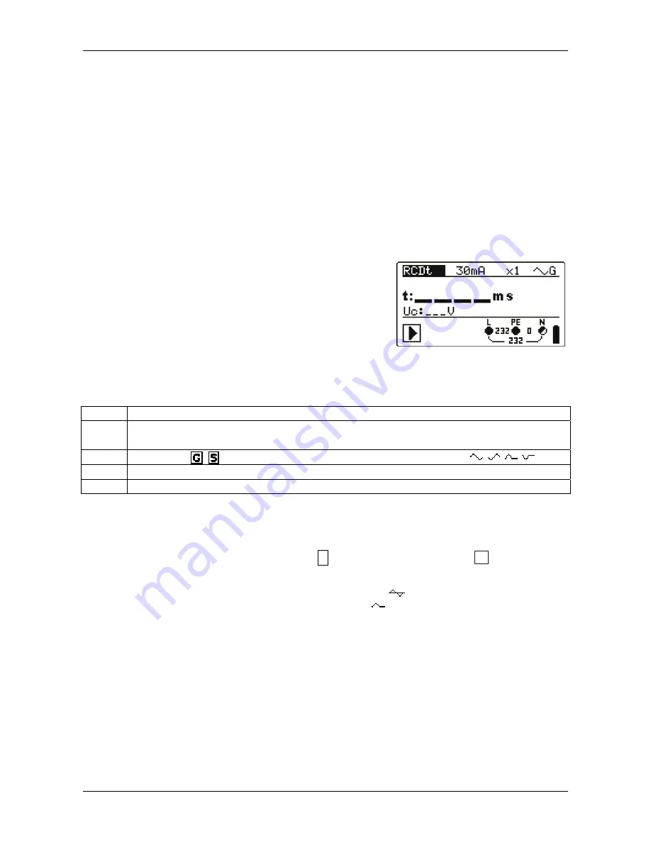
Figure 5.1: RCD test
Test parameters for RCD test and measurement
TEST RCD
sub-function
test [RCDt, RCD I, AUTO, Uc].
I
N
Rated
RCD residual current sensitivity I
N
[10 mA, 30 mA, 100 mA, 300 mA,
500 mA, 1000 mA].
type
RCD
type
[ , ]
,
test current
waveform
plus
starting
polarity
[
,
,
,
]
.
MUL
Multiplication
factor for test current [½, 1, 2, 5 I
N
].
Ulim Conventional
touch
voltage
limit
[25 V, 50 V].
Notes
:
Ulim can be selected in the Uc sub-function only.
The instrument is intended for testing of
G
eneral (non-delayed) and
S
elective (time-
delayed) RCDs, which are suited for:
Alternating residual current (AC type, marked with
symbol),
Pulsating residual current (A type, marked with symbol).
Time delayed RCDs have delayed response characteristics. As the contact voltage
pre-test or other RCD tests influence the time delayed RCD it takes a certain period
to recover into normal state. Therefore a time delay of 30 s is inserted before
performing trip-out test by default.


