Electrical Installation Safety Trainer
AD 1 - MI 3399
106
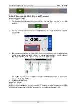
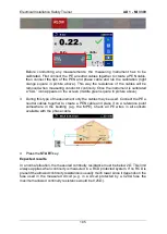
Since continuity was measured in a RCD protected TN system the measured value is
regarded as passed.
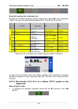
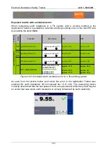
Expected results with a simulated error
A typical fault when measuring continuity would be if the resistance of PE conductor
would be above 2
Ω. To simulate such an error enable the switch
S19
in the Application
Trainer.
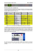
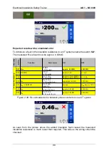
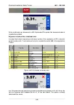
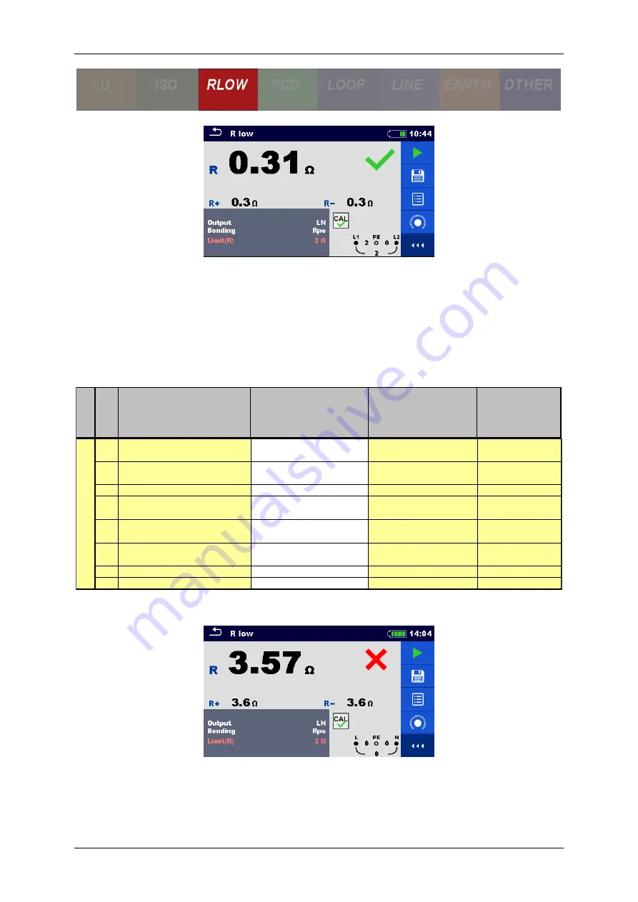
Figure 2-45: Simulated continuity error
In a TN system the simulated error introduced additional resistance of 3.4
Ω. Since the
limit for systems with installed RCD is 2
Ω the test failed. The device correctly
interpreted the result.
E
xer
ci
ses
S
w
itch
Function
Site of error
ON
OFF
S15 R LOW / IMD
IT F3/1
PE outlet
> 20
Ω
< 1
Ω
S16 ISFL / IMD
IT F3/2
ISFL
approx. 6 mA (@ 230 V)
approx. 3 mA (@ 115 V)
< 1.3 mA
S17 R LOW
IT PE ref.
approx. 3.3 Ω
< 1 Ω
S18 R LOW
TN/TT F1/4
PE light
> 20
Ω
< 1 Ω
S19 R LOW / Z LOOP
TN/TT F1/2
PE outlet (3-ph.)
approx. 3.4 Ω
< 1 Ω
S20 R LOW / Z LOOP
TN/TT F2/2
PE outlet
> 2.3
Ω
< 2 Ω
S21 R LOW
MPE / PE Gas
approx. 2.2 Ω
< 1 Ω
S22 R LOW
MPE / PE Heat inst.
approx. 3.3 Ω
< 1 Ω
P
E
C
o
n
n
e
c
tio
n
Summary of Contents for MI 3399
Page 27: ...Electrical Installation Safety Trainer AD 1 MI 3399 27...
Page 46: ...Electrical Installation Safety Trainer AD 1 MI 3399 46 3 Exit settings...
Page 74: ...Electrical Installation Safety Trainer AD 1 MI 3399 74...
Page 197: ...Power and Voltage Quality Trainer AD 2 MI 3399 197 Figure 4 89 Transient Chart view...
Page 204: ...PAT Appliances Machines Safety Trainer AD 3 MI 3399 204...
Page 249: ...PV Photovoltaic Systems Trainer AD 4 MI 3399 249...
Page 250: ...PV Photovoltaic Systems Trainer AD 4 MI 3399 250 AD 4 MI 3399 PV Photovoltaic Systems Trainer...

