Electrical Installation Safety Trainer
AD 1 - MI 3399
112
𝑅
𝐿𝑂𝑂𝑃
= 𝑅
𝐿𝐻
+ 𝑅
𝐸𝐻
+ 𝑅
𝐸𝐷
+ 𝑅
𝑇
[Ω]
If the total earth resistance of R
EH
is higher than the resistance R
ED
and the return path
(resistance of L conductors, secondary of power transformer) then the result can be
considered as
R
EH
.
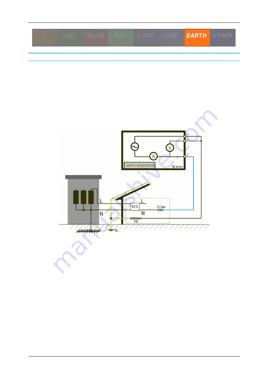
This test is applicable:
Applicable for TT systems, where the measured installation’s earthing resistance is
higher than the (well grounded) auxiliary one.
Applicable in urban areas if there is no appropriate place for test probes.
Applicable in areas where different local earthings are connected together, making
the local earthing system very large.
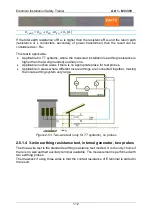
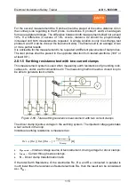
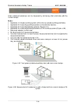
Figure 2-51: Two-wire test (only for TT systems), no probes
2.8.1.4 3-wire earthing resistance test, internal generator, two probes
The three-wire test is the standard earthing resistance test method. It is the only choice if
there is no well earthed auxiliary terminal available. The measurement is performed with
two earthing probes.
The drawback if using three wires is that the contact resistance of E terminal is added to
the result.
Summary of Contents for MI 3399
Page 27: ...Electrical Installation Safety Trainer AD 1 MI 3399 27...
Page 46: ...Electrical Installation Safety Trainer AD 1 MI 3399 46 3 Exit settings...
Page 74: ...Electrical Installation Safety Trainer AD 1 MI 3399 74...
Page 197: ...Power and Voltage Quality Trainer AD 2 MI 3399 197 Figure 4 89 Transient Chart view...
Page 204: ...PAT Appliances Machines Safety Trainer AD 3 MI 3399 204...
Page 249: ...PV Photovoltaic Systems Trainer AD 4 MI 3399 249...
Page 250: ...PV Photovoltaic Systems Trainer AD 4 MI 3399 250 AD 4 MI 3399 PV Photovoltaic Systems Trainer...

