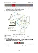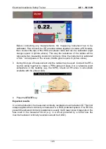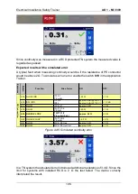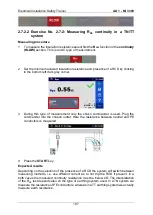
Electrical Installation Safety Trainer
AD 1 - MI 3399
113
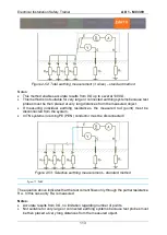
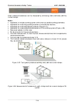
Figure 2-52: Total earthing measurement (3 wires)
– standard method
Notes:
This method enables accurate results from 0
Ω up to several 1000 Ω.
This method is not suitable for very large or connected earthing systems because test
probes must be then placed at very long distances from the measured object.
If measuring individual earthing resistances, the measured rod (point) must be
disconnected from the system.
In TN systems incoming PE (PEN) conductor must be disconnected!
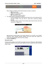
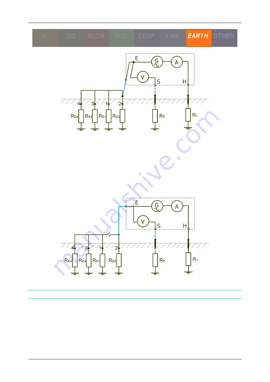
Figure 2-53: Selective earthing measurement
– standard method
𝐼
𝑔𝑒𝑛
= 𝐼
𝑅𝐸2
The equation above indicates that the test current flows only through the partial resistance
R
E2
. In this case only R
E2
is measured.
Notes:
Accurate results from 0
Ω, no limitation regarding number of points.
Not suitable for very large or connected earthing systems because test probes must
be then placed at very long distances from the measured object.
Summary of Contents for MI 3399
Page 27: ...Electrical Installation Safety Trainer AD 1 MI 3399 27...
Page 46: ...Electrical Installation Safety Trainer AD 1 MI 3399 46 3 Exit settings...
Page 74: ...Electrical Installation Safety Trainer AD 1 MI 3399 74...
Page 197: ...Power and Voltage Quality Trainer AD 2 MI 3399 197 Figure 4 89 Transient Chart view...
Page 204: ...PAT Appliances Machines Safety Trainer AD 3 MI 3399 204...
Page 249: ...PV Photovoltaic Systems Trainer AD 4 MI 3399 249...
Page 250: ...PV Photovoltaic Systems Trainer AD 4 MI 3399 250 AD 4 MI 3399 PV Photovoltaic Systems Trainer...

