Electrical Installation Safety Trainer
AD 1 - MI 3399
116
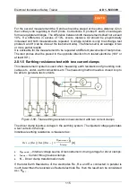
Other individual resistances can be measured by embracing other electrodes with the
current clamps.
Notes:
Applicable in complex earthing system with numerous parallel earthing electrodes.
Applicable for measuring earthing resistance in transformer stations.
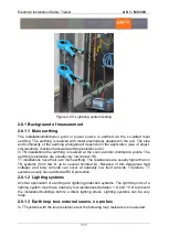
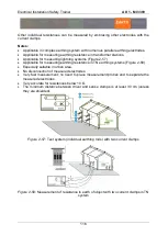
Applicable for measuring lightning systems (Figure 2-57).
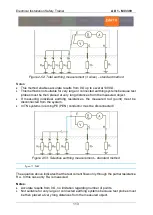
Applicable for measuring earthing resistance in TN earthing systems (Figure 2-58).
Especially suitable in urban area.
No disconnection of measured electrodes.
Very fast measurement; no need to place measurement probes and to separate the
measured electrodes.
Very accurate for resistances below 10 Ω.
The minimum distance between driver and sense clamps is at least 30 cm (unless
they are shielded).
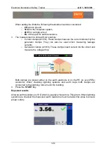
Figure 2-57:
Test system (individual earthing rods) with two current clamps
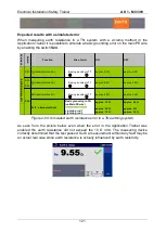
Figure 2-58:
Measurement of resistance to earth of object with two current clamps in TN
system
Summary of Contents for MI 3399
Page 27: ...Electrical Installation Safety Trainer AD 1 MI 3399 27...
Page 46: ...Electrical Installation Safety Trainer AD 1 MI 3399 46 3 Exit settings...
Page 74: ...Electrical Installation Safety Trainer AD 1 MI 3399 74...
Page 197: ...Power and Voltage Quality Trainer AD 2 MI 3399 197 Figure 4 89 Transient Chart view...
Page 204: ...PAT Appliances Machines Safety Trainer AD 3 MI 3399 204...
Page 249: ...PV Photovoltaic Systems Trainer AD 4 MI 3399 249...
Page 250: ...PV Photovoltaic Systems Trainer AD 4 MI 3399 250 AD 4 MI 3399 PV Photovoltaic Systems Trainer...

