Electrical Installation Safety Trainer
AD 1 - MI 3399
117
2.8.2 Exercises
2.8.2.1 Exercise No. 2.8-1: Earth Resistance Measurement
– three wire
method
Measuring procedure
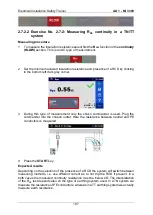
1
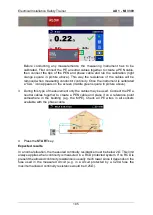
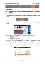
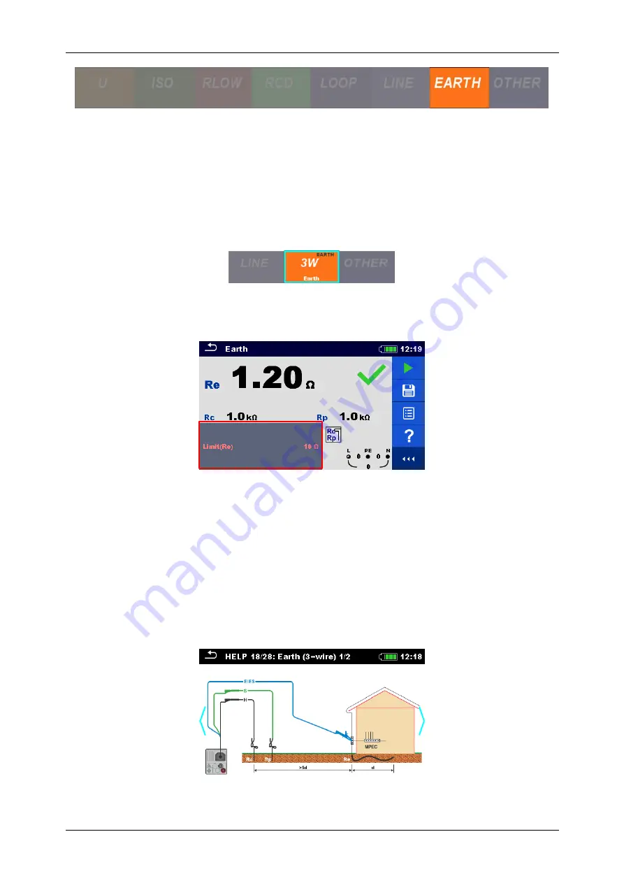
To measure the earth resistance select first the
3W (three wire)
function in the
Earth
section.
2
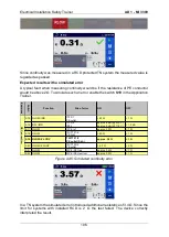
Set the maximum allowed earth resistance by clicking in the bottom left dark grey
corner.
When setting the limits the following thresholds should be considered:
o
2
Ω
above ground,
o
10
Ω
for the complete system,
o
20
Ω
for a single wire or
o
8%
of the specific earth resistance.
3
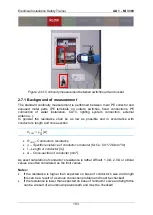
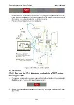
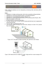
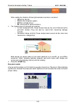
During this type of measurement cables in combination with earth probes are to be
used. Plug the neutral cable to the PE conductor or the earthing rod. Connect the
phase cable to one probe and the PE cable to the other probe. After the measurement
is completed reverse the cables connected to both rods in order to exclude any funnel
overlap. If the measured resistances are equal (20% to 30% difference is acceptable),
funnel overlap is not present.
Summary of Contents for MI 3399
Page 27: ...Electrical Installation Safety Trainer AD 1 MI 3399 27...
Page 46: ...Electrical Installation Safety Trainer AD 1 MI 3399 46 3 Exit settings...
Page 74: ...Electrical Installation Safety Trainer AD 1 MI 3399 74...
Page 197: ...Power and Voltage Quality Trainer AD 2 MI 3399 197 Figure 4 89 Transient Chart view...
Page 204: ...PAT Appliances Machines Safety Trainer AD 3 MI 3399 204...
Page 249: ...PV Photovoltaic Systems Trainer AD 4 MI 3399 249...
Page 250: ...PV Photovoltaic Systems Trainer AD 4 MI 3399 250 AD 4 MI 3399 PV Photovoltaic Systems Trainer...

