Electrical Installation Safety Trainer
AD 1 - MI 3399
120
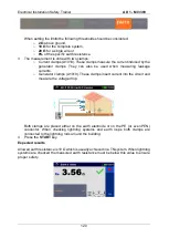
When setting the limits the following thresholds should be considered:
o
2
Ω
above ground,
o
10
Ω
for the complete system,
o
20
Ω
for a single wire or
o
8%
of the specific earth resistance.
3
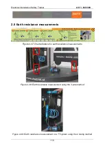
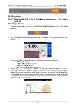
The measurement is done with two clamps:
o
Current clamps (A1018). These clamps measure the current induced by the
generator clamps. They can also be used when measuring leakage
currents.
o
Generator clamps (A1019). These clamps insert current into the circuit and
measure the voltage drop.
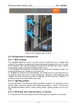
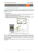
Both clamps are placed either on the earth electrode or on the PE (or even PEN)
conductor. When checking lightning systems and earth loops both clamps are
connected to the lightning rods around the building.
4
Press the
START
key.
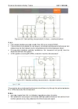
Expected results
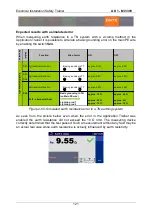
Allowed earth resistance is 10
Ω which is usually achieved in a TN system. When lightning
systems are checked the measured earth resistance must be below this value to ensure
proper safety.
Summary of Contents for MI 3399
Page 27: ...Electrical Installation Safety Trainer AD 1 MI 3399 27...
Page 46: ...Electrical Installation Safety Trainer AD 1 MI 3399 46 3 Exit settings...
Page 74: ...Electrical Installation Safety Trainer AD 1 MI 3399 74...
Page 197: ...Power and Voltage Quality Trainer AD 2 MI 3399 197 Figure 4 89 Transient Chart view...
Page 204: ...PAT Appliances Machines Safety Trainer AD 3 MI 3399 204...
Page 249: ...PV Photovoltaic Systems Trainer AD 4 MI 3399 249...
Page 250: ...PV Photovoltaic Systems Trainer AD 4 MI 3399 250 AD 4 MI 3399 PV Photovoltaic Systems Trainer...

