Power and Voltage Quality Trainer
AD 2
– MI 3399
201
N
?
L?
L?
L?
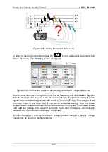
Figure 4-96: Wrong instrument connection
In order to resolve this problem press the
button and select the Connection
Check menu line. The following screen will appear:
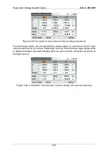
Figure 4-97: Connection check screen (wrong current and voltage sequence)
Here the user can check Voltage, Current, Power, frequency and other values, together
with phase angle and sequence. All measurements are checked according to some
logical limits and status is given as with an OK ( ) or Fail ( ) sign. For example: if we
monitor a motor or any other kind of load (which consumes energy), then the phase
angle between voltage and current should be less than 90 degrees. In our case, phase
shift between voltage and adjacent current is more than 90 degree, which clearly
indicates that the instrument is wrongly connected.
By interchanging L1 and L2 instrument voltage probes, we get a proper voltage
connection, as shown in the figure below.
Summary of Contents for MI 3399
Page 27: ...Electrical Installation Safety Trainer AD 1 MI 3399 27...
Page 46: ...Electrical Installation Safety Trainer AD 1 MI 3399 46 3 Exit settings...
Page 74: ...Electrical Installation Safety Trainer AD 1 MI 3399 74...
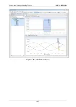
Page 197: ...Power and Voltage Quality Trainer AD 2 MI 3399 197 Figure 4 89 Transient Chart view...
Page 204: ...PAT Appliances Machines Safety Trainer AD 3 MI 3399 204...
Page 249: ...PV Photovoltaic Systems Trainer AD 4 MI 3399 249...
Page 250: ...PV Photovoltaic Systems Trainer AD 4 MI 3399 250 AD 4 MI 3399 PV Photovoltaic Systems Trainer...


