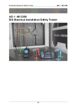
Electrical Installation Safety Trainer
AD 1 - MI 3399
31
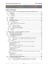
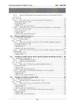
2.6.2.3
Exercise No. 2.6-3: R
ISO
in an IT system ................................................................................ 97
Measuring procedure ......................................................................................................................... 97
Expected results ................................................................................................................................. 97
Expected results with a simulated error ............................................................................................ 98
2.6.2.4
Exercise No. 2.6-4: R
ISO
varistor measurement .................................................................... 99
Measuring procedure ......................................................................................................................... 99
Expected results ............................................................................................................................... 100
Expected results with a simulated error .......................................................................................... 101
2.7
Conductor continuity measurement ................................................................ 102
2.7.1
Background of measurement ...................................................................................................... 103
2.7.2
Exercises ...................................................................................................................................... 104
2.7.2.1
Exercise No. 2.7-1: Measuring continuity in a TN/TT system ............................................ 104
Measuring procedure ....................................................................................................................... 104
Expected results ............................................................................................................................... 105
Expected results with a simulated error .......................................................................................... 106
2.7.2.2
Exercise No. 2.7-2: Measuring R
PE
continuity in a TN/TT system....................................... 107
Measuring procedure ....................................................................................................................... 107
Expected results ............................................................................................................................... 107
Expected results with a simulated error .......................................................................................... 108
2.8
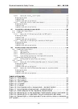
Earth resistance measurements ...................................................................... 110
2.8.1
Background of measurement ...................................................................................................... 111
2.8.1.1
Main earthing .................................................................................................................... 111
2.8.1.2
Lighting systems................................................................................................................. 111
2.8.1.3
Earth loop test, external source, no probes ...................................................................... 111
2.8.1.4
3-wire earthing resistance test, internal generator, two probes ...................................... 112
Functionality and placing of test probes .......................................................................................... 114
2.8.1.5
Earthing resistance test with two current clamps ............................................................. 115
2.8.2
Exercises ...................................................................................................................................... 117
2.8.2.1
Exercise No. 2.8-1: Earth Resistance Measurement – three wire method ........................ 117
Measuring procedure ....................................................................................................................... 117
Expected results ............................................................................................................................... 118
Expected results with a simulated error .......................................................................................... 118
2.8.2.2
Exercise No. 2.8-2: Earth Resistance Measurement – two clamp method ........................ 119
Measuring procedure ....................................................................................................................... 119
Expected results ............................................................................................................................... 120
Expected results with a simulated error .......................................................................................... 121
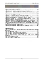
TABLE OF FIGURES:
– standard method ........................ 39
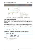
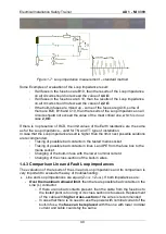
Figure 1-7: Loop impedance measurement
– standard method ............................... 40
Figure 2-1: Chart reference for line impedance measurements ................................ 47
in the Application Trainer with the schuko commander . 47
in Application Trainer’s switchboard with cables ........... 48
Summary of Contents for MI 3399
Page 27: ...Electrical Installation Safety Trainer AD 1 MI 3399 27...
Page 46: ...Electrical Installation Safety Trainer AD 1 MI 3399 46 3 Exit settings...
Page 74: ...Electrical Installation Safety Trainer AD 1 MI 3399 74...
Page 197: ...Power and Voltage Quality Trainer AD 2 MI 3399 197 Figure 4 89 Transient Chart view...
Page 204: ...PAT Appliances Machines Safety Trainer AD 3 MI 3399 204...
Page 249: ...PV Photovoltaic Systems Trainer AD 4 MI 3399 249...
Page 250: ...PV Photovoltaic Systems Trainer AD 4 MI 3399 250 AD 4 MI 3399 PV Photovoltaic Systems Trainer...


