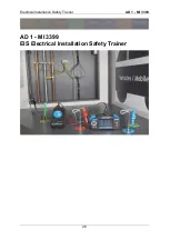
Electrical Installation Safety Trainer
AD 1 - MI 3399
40
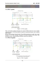
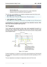
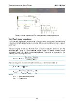
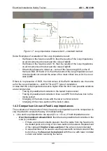
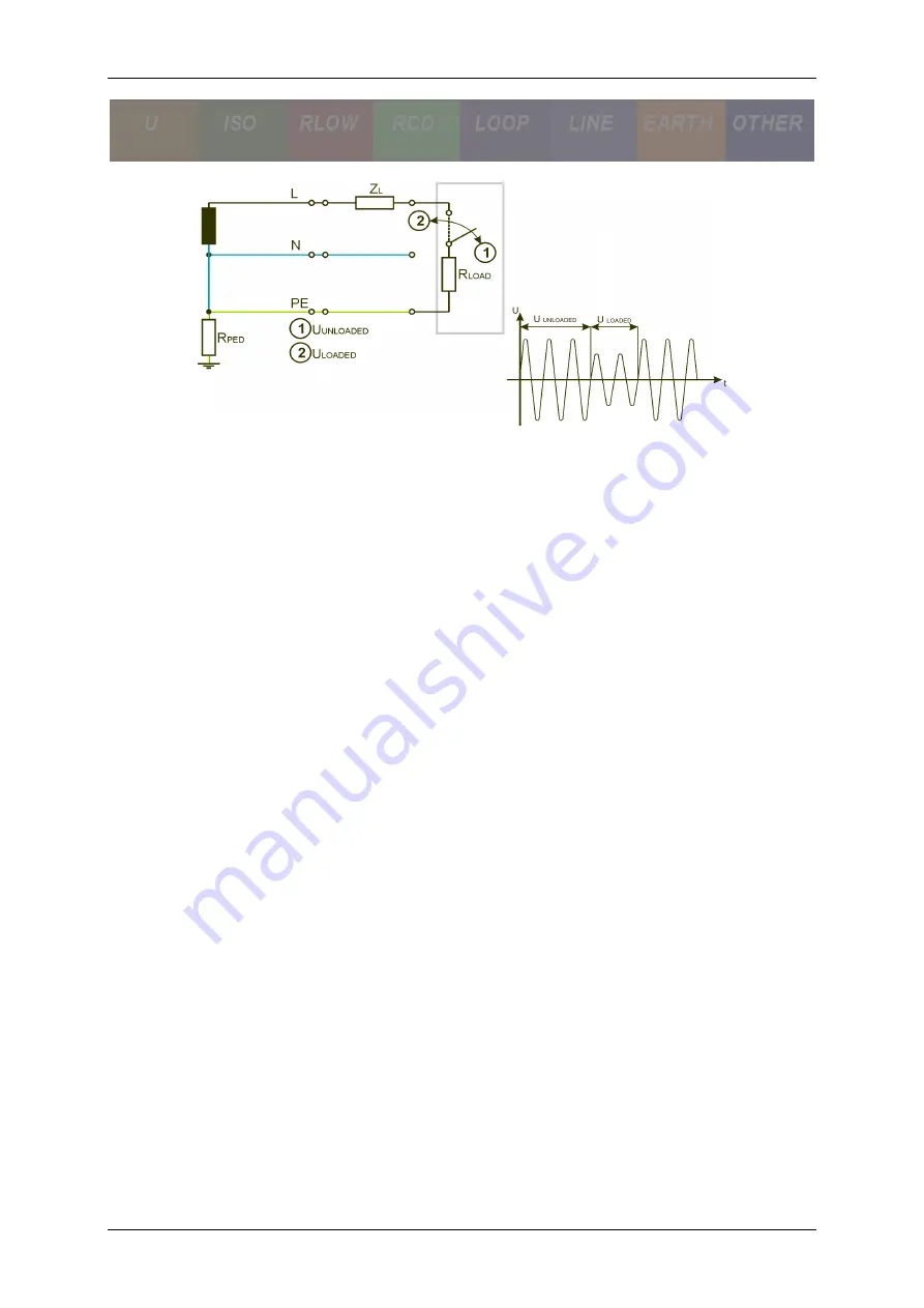
Figure 1-7: Loop impedance measurement
– standard method
Some Examples of evaluation of the Loop impedance result:
-
If all fuses in the fuse box are B10, than the results of the Loop impedance
on all circuits should not exceed the value of
4,4 Ω
.
-
If all fuses in the fuse box are C10, than the results of the Loop impedance
on all circuits should not exceed the value of
2
,2 Ω
.
-
If the built-in fuses are mixed up - some of the fuses are gG16, some of
them are B20, B16 and C10, than the results of the Loop impedance on all
circuits should not exceed the value of the most critical one, which is in our
case
2,0 Ω
.
If there is no presence of RCD, the limit values of the Earth resistance are the same
as for the Loop impedance
– valid for TN and TT type of installation.
In case that the Loop impedance result is higher than the limit, next possible solutions
are recommended:
-
Tracing of possible bad contacts in the tested mains socket.
-
Tracing of possible bad contacts in lines L and PE from the fuse box to the
mains socket.
-
Changing of the built-in fuse with the lower nominal current.
-
Changing of the cross-section of the built-in wires.
1.4.3 Comparison Line and Fault Loop impedances
The evaluation of the results of the Line and Loop impedance and its comparison is
very important to evaluate the way of troubleshooting:
Line and Loop impedances are equal (Z
LOOP
= Z
LINE
). If both impedances are:
-
Over the maximum allowed limit
, then there are possible bad contacts on the
Line (L) conductor.
o
If there are no bad contacts present, then the cable from the fuse box to
the tested point is too long or its cross-section is too week. Replacement
of the cable with
higher cross-section
of the wires is recommended
o
In case that there is no need to use the power with nominal current of the
built-in fuse, the
fuse can be replaced
with the one with lower nominal
current and cable could stay the same.
Summary of Contents for MI 3399
Page 27: ...Electrical Installation Safety Trainer AD 1 MI 3399 27...
Page 46: ...Electrical Installation Safety Trainer AD 1 MI 3399 46 3 Exit settings...
Page 74: ...Electrical Installation Safety Trainer AD 1 MI 3399 74...
Page 197: ...Power and Voltage Quality Trainer AD 2 MI 3399 197 Figure 4 89 Transient Chart view...
Page 204: ...PAT Appliances Machines Safety Trainer AD 3 MI 3399 204...
Page 249: ...PV Photovoltaic Systems Trainer AD 4 MI 3399 249...
Page 250: ...PV Photovoltaic Systems Trainer AD 4 MI 3399 250 AD 4 MI 3399 PV Photovoltaic Systems Trainer...

