Electrical Installation Safety Trainer
AD 1 - MI 3399
45
2 Measurements on electrical installations in
practice
This chapter describes basic principles of measuring electrical installations in buildings
in TN, TT and IT earthing systems. Although the sequence of measurements follows a
logical order from impedance toward earth resistance, the correct order when
conducting a first inspection of installations (and recommended order at periodical
testing) is as follows:
1. Continuity testing (R
LOW
)
2. Insulations resistance (R
ISO
)
3. Line impedance (Z
LINE
)
4. Fault loop impedance (Z
LOOP
)
5. RCD testing
6. Earth resistance testing
7. IMD and ISFL testing
8. Voltage testing
2.1
Instrument’s general settings
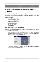
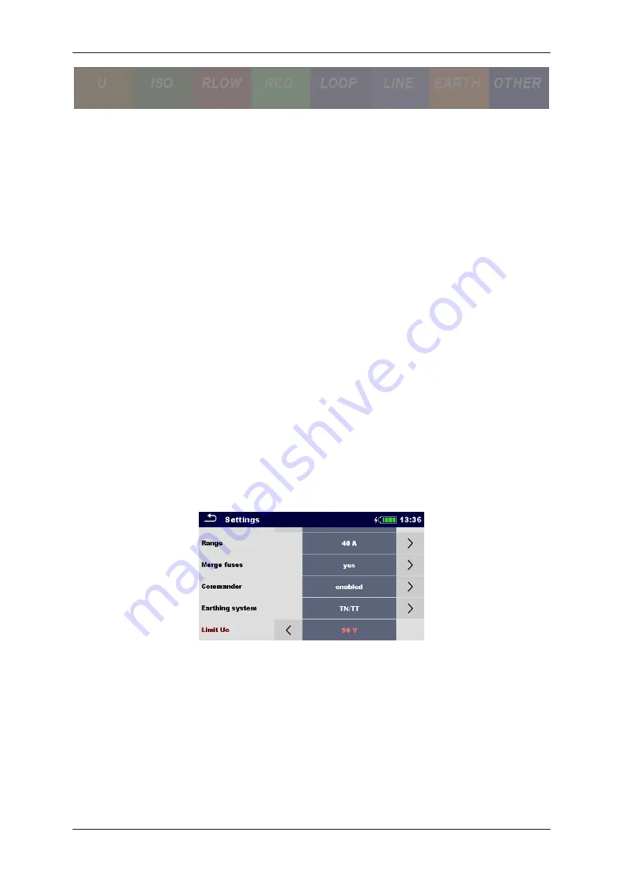
Depending on the earthing system being tested the appropriate system must be also
set on the instrument. To do so:
1. Power on the device used for testing and navigate to the settings menu. Scroll
down to the bottom of the menu where the Earthing system may be selected.
The chosen value can be either
TN/TT
or
IT
.
2. If the earthing system used is TN or TT, select the
TN/TT
option. If the earthing
system used is IT, select the
IT
option.
Summary of Contents for MI 3399
Page 27: ...Electrical Installation Safety Trainer AD 1 MI 3399 27...
Page 46: ...Electrical Installation Safety Trainer AD 1 MI 3399 46 3 Exit settings...
Page 74: ...Electrical Installation Safety Trainer AD 1 MI 3399 74...
Page 197: ...Power and Voltage Quality Trainer AD 2 MI 3399 197 Figure 4 89 Transient Chart view...
Page 204: ...PAT Appliances Machines Safety Trainer AD 3 MI 3399 204...
Page 249: ...PV Photovoltaic Systems Trainer AD 4 MI 3399 249...
Page 250: ...PV Photovoltaic Systems Trainer AD 4 MI 3399 250 AD 4 MI 3399 PV Photovoltaic Systems Trainer...

