Electrical Installation Safety Trainer
AD 1 - MI 3399
54
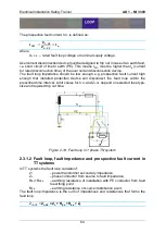
𝑰
𝑷𝑺𝑪
=
𝑼
𝑵
𝒁
𝑴𝑬𝑨𝑺𝑼𝑹𝑬𝑫
where:
U
N
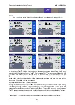
– nominal value, determined according to the measured voltage (U
L-N
).
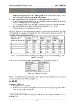
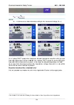
In a 1-phase TN/TT system the maximum allowed impedance result for a 6A gG type
fuse with 400ms trip-out time is
4,6
Ω
4
. If a 3-phase TN/TT system is used a 6A B type
fuse with 200ms trip-out time is used. In this case the allowed impedance is
7,3
Ω
.
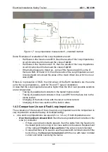
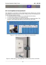
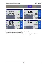
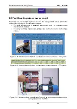
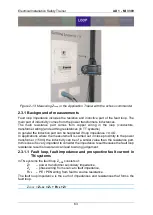
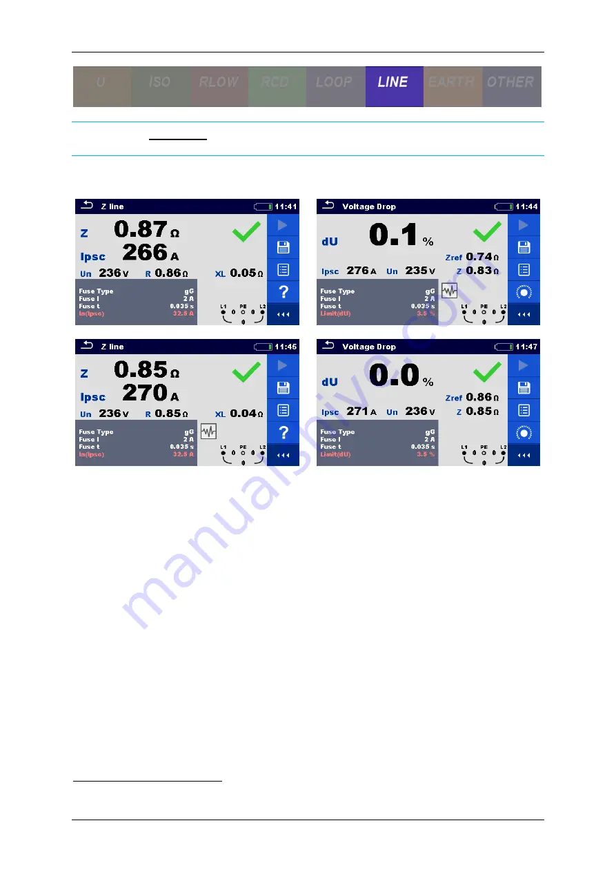
As is seen from the screens above the impedance, voltage drop and I
PSC
are within
limits and the test is marked as passed.
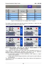
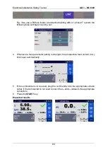
Expected results with a simulated error
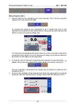
It is not possible to simulate an error in the Application Trainer on the supply side.
4
See chapter 1.4 Ensurance of Safety for more details on fuse trip-out times and impedances.
Summary of Contents for MI 3399
Page 27: ...Electrical Installation Safety Trainer AD 1 MI 3399 27...
Page 46: ...Electrical Installation Safety Trainer AD 1 MI 3399 46 3 Exit settings...
Page 74: ...Electrical Installation Safety Trainer AD 1 MI 3399 74...
Page 197: ...Power and Voltage Quality Trainer AD 2 MI 3399 197 Figure 4 89 Transient Chart view...
Page 204: ...PAT Appliances Machines Safety Trainer AD 3 MI 3399 204...
Page 249: ...PV Photovoltaic Systems Trainer AD 4 MI 3399 249...
Page 250: ...PV Photovoltaic Systems Trainer AD 4 MI 3399 250 AD 4 MI 3399 PV Photovoltaic Systems Trainer...

