Electrical Installation Safety Trainer
AD 1 - MI 3399
58
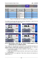
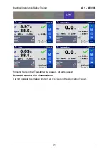
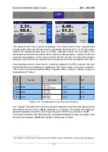
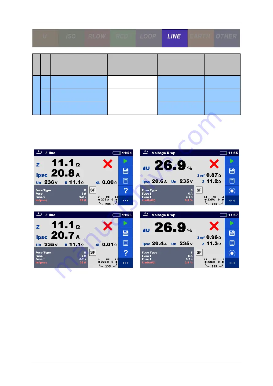
Figure 2-9: Simulated error on a 3-phase TN or TT system
The result is that the test fails since the measured impedance is higher than the
maximum allowed (
7,3
Ω
) for this type of fuse.
2.2.3.3 Exercise No. 2.2-3: dU, Z
L-N
and I
PSC
measurement on the
socket side in an IT earthing system
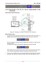
The IT system has the supply part of the power source separated from earth or is
earthed through a sufficient high impedance at the source. The line impedance
depends on the size of the system and size of the transformer used:
A small system requires a smaller transformer, which results in a higher
reference line impedance.
A large system requires a larger transformer, which results in a lower reference
line impedance.
This exercise is done on the Application Trainer whose reference line impedance is
approximately 7
Ω.
E
xer
ci
ses
S
w
itch
Function
Site of error
ON
OFF
S12 Z LINE
TN/TT F1/2
L3/N outlet (3-ph.)
> 10
Ω
< 2
Ω
S13 Z LINE
TN/TT F2/2
L1/N outlet
> 10
Ω
< 2
Ω
S14 Z LINE
TN/TT F1/3
L3/N outlet
> 10
Ω
< 2
Ω
L
in
e
Im
p
e
d
a
n
c
e
Summary of Contents for MI 3399
Page 27: ...Electrical Installation Safety Trainer AD 1 MI 3399 27...
Page 46: ...Electrical Installation Safety Trainer AD 1 MI 3399 46 3 Exit settings...
Page 74: ...Electrical Installation Safety Trainer AD 1 MI 3399 74...
Page 197: ...Power and Voltage Quality Trainer AD 2 MI 3399 197 Figure 4 89 Transient Chart view...
Page 204: ...PAT Appliances Machines Safety Trainer AD 3 MI 3399 204...
Page 249: ...PV Photovoltaic Systems Trainer AD 4 MI 3399 249...
Page 250: ...PV Photovoltaic Systems Trainer AD 4 MI 3399 250 AD 4 MI 3399 PV Photovoltaic Systems Trainer...

