Electrical Installation Safety Trainer
AD 1 - MI 3399
63
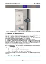
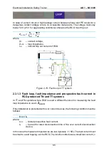
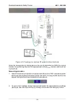
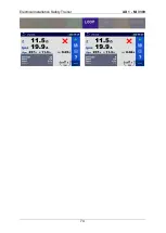
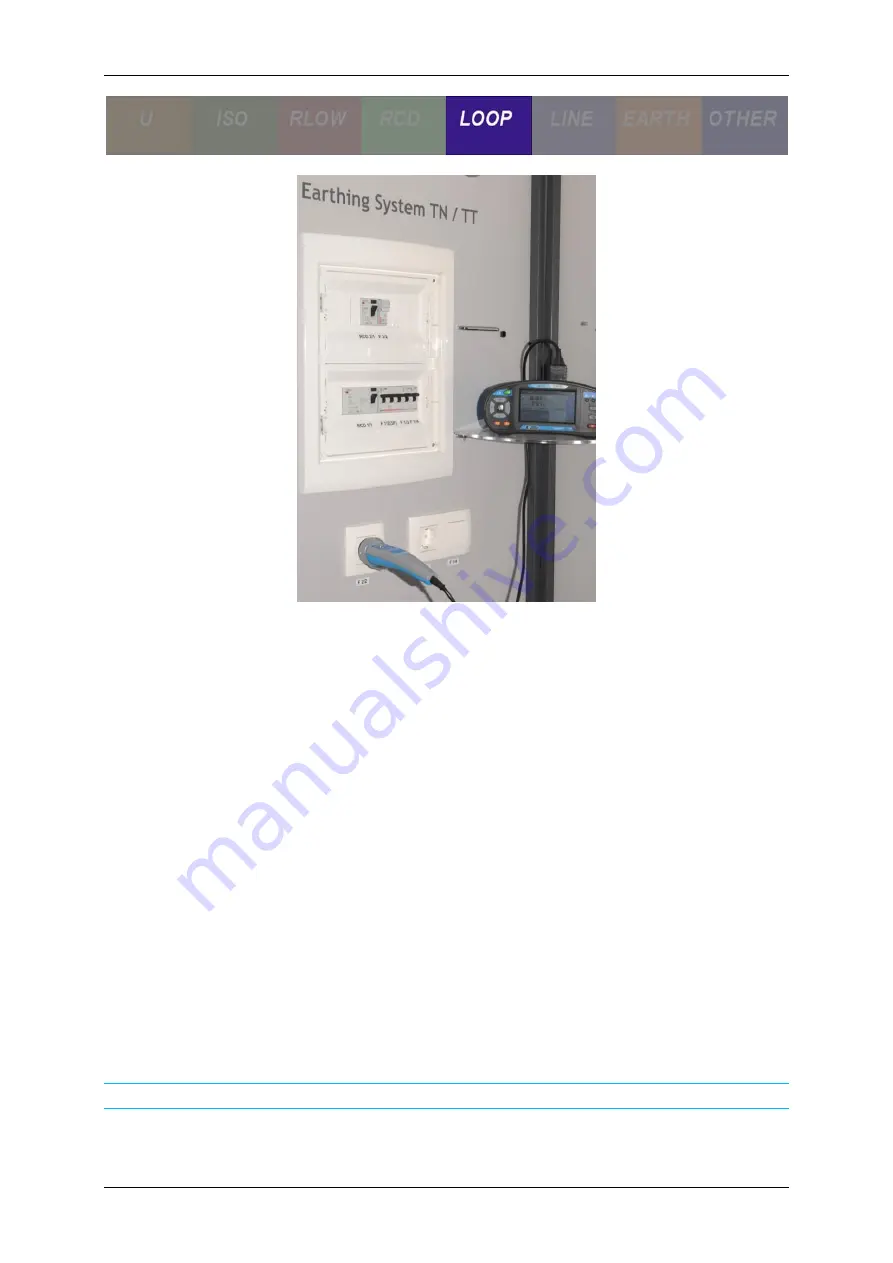
Figure 2-13: Measuring Z
Loop
in the Application Trainer with the schuko commander
2.3.1 Background of measurements
Fault loop impedance includes the resistive and inductive part of the fault loop. The
main part of inductivity comes from the power transformers inductances.
The main resistance part comes from copper wiring in the loop (conductors,
transformer wiring) and earthing resistances (in TT systems).
In general the inductive part can be neglected if loop impedance > 0.4 Ω.
In applications where the measurement is carried out in close proximity to the power
transformer (< 50m) the inductivity can be of a similar value than the resistance part.
In this case it is very important to consider the impedance result because the fault loop
resistance result is lower and can lead to wrong judgement.
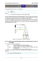
2.3.1.1 Fault loop, fault impedance and prospective fault current in
TN systems
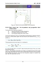
In TN systems the fault loop Z
L-PE
consists of:
Z
T
– power transformer secondary impedance,
Z
L
– phase wiring from source to fault impedance,
R
PE
– PE / PEN wiring from fault to source resistance.
The fault loop impedance is the sum of impedances and resistances that forms the
fault loop.
Z
LOOP
=
Z
L-PE
= Z
L
+ R
PE
+ Z
T
Summary of Contents for MI 3399
Page 27: ...Electrical Installation Safety Trainer AD 1 MI 3399 27...
Page 46: ...Electrical Installation Safety Trainer AD 1 MI 3399 46 3 Exit settings...
Page 74: ...Electrical Installation Safety Trainer AD 1 MI 3399 74...
Page 197: ...Power and Voltage Quality Trainer AD 2 MI 3399 197 Figure 4 89 Transient Chart view...
Page 204: ...PAT Appliances Machines Safety Trainer AD 3 MI 3399 204...
Page 249: ...PV Photovoltaic Systems Trainer AD 4 MI 3399 249...
Page 250: ...PV Photovoltaic Systems Trainer AD 4 MI 3399 250 AD 4 MI 3399 PV Photovoltaic Systems Trainer...

