Electrical Installation Safety Trainer
AD 1 - MI 3399
64
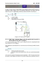
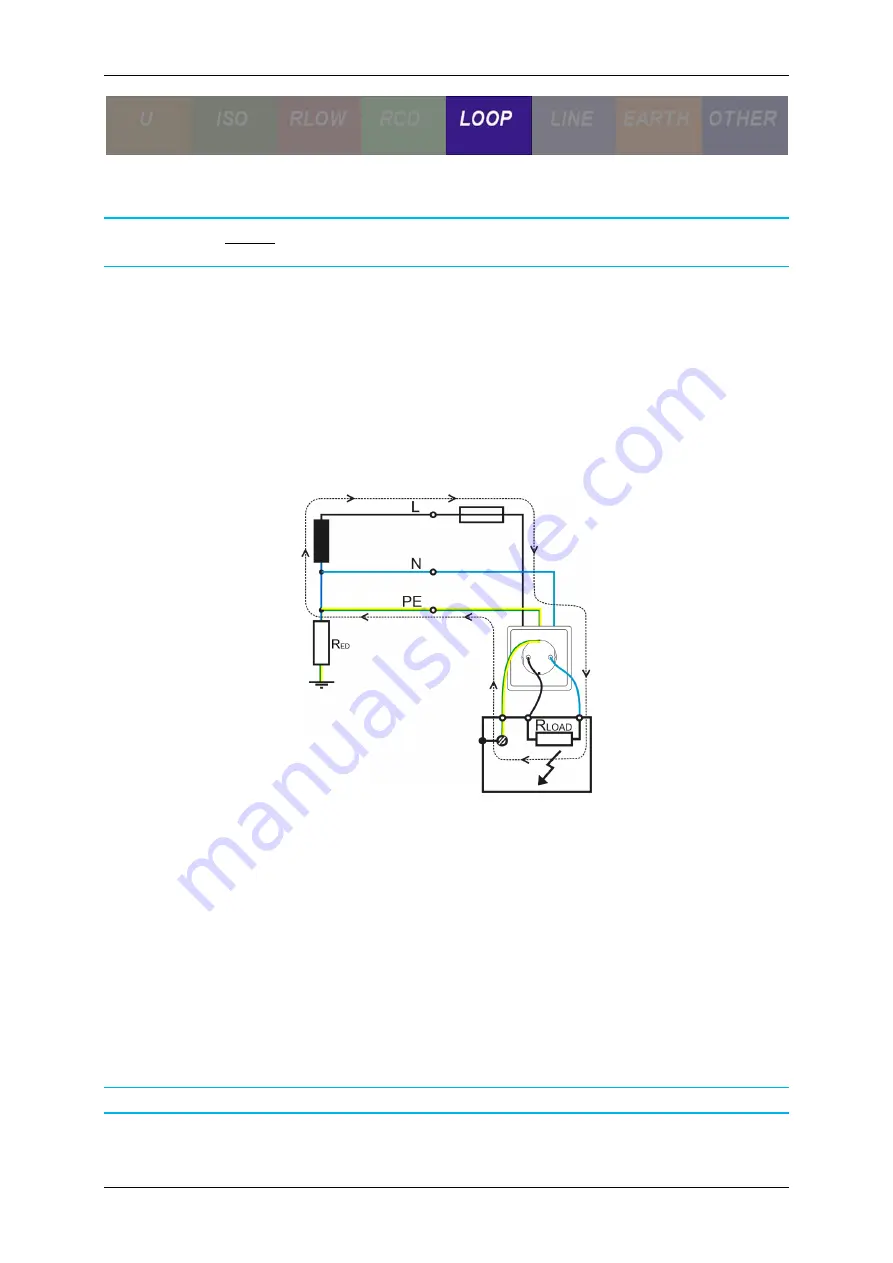
The prospective fault current I
PFC
is defined as:
𝑰
𝑷𝑭𝑪
=
𝑼
𝑳−𝑷𝑬
𝒁
𝑳−𝑷𝑬
> 𝑰
𝒂
where
U
L-PE
– rated fault loop voltage or nominal supply voltage.
Overcurrent disconnection device must be designed to trip out in case of an earth fault,
i.e. short circuit of line to earth (PE). This means I
PFC
must be higher than I
a
(current
for rated disconnection time) of the over current disconnection device.
The fault loop impedance should be low enough e.g. prospective fault current high
enough that installed protection device will disconnect the fault loop within the
prescribed time interval. Limit values for I
PFC
and Z
L-PE
depend on selected fuse type,
size and required trip out time.
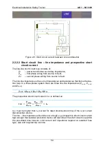
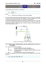
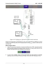
Figure 2-14: Fault loop in 1 phase TN system
2.3.1.2 Fault loop, fault impedance and prospective fault current in
TT systems
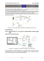
In TT systems the fault loop consists of:
Z
T
– power transformer secondary impedance,
Z
L
– phase conductor from source to fault impedance,
R
Eh
+R
PEh
– earthing resistance of installation with PE conductor from fault
to earthing point,
R
Ed
– earthing resistance of source/ distribution point.
The fault loop impedance is the sum of impedances and resistances that forms the
fault loop.
Z
LOOP
=
Z
L-PE
= Z
L
+ R
Eh
+ R
Ed
+ Z
T
Summary of Contents for MI 3399
Page 27: ...Electrical Installation Safety Trainer AD 1 MI 3399 27...
Page 46: ...Electrical Installation Safety Trainer AD 1 MI 3399 46 3 Exit settings...
Page 74: ...Electrical Installation Safety Trainer AD 1 MI 3399 74...
Page 197: ...Power and Voltage Quality Trainer AD 2 MI 3399 197 Figure 4 89 Transient Chart view...
Page 204: ...PAT Appliances Machines Safety Trainer AD 3 MI 3399 204...
Page 249: ...PV Photovoltaic Systems Trainer AD 4 MI 3399 249...
Page 250: ...PV Photovoltaic Systems Trainer AD 4 MI 3399 250 AD 4 MI 3399 PV Photovoltaic Systems Trainer...

