Electrical Installation Safety Trainer
AD 1 - MI 3399
67
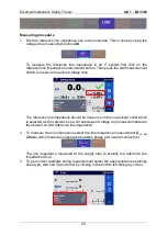
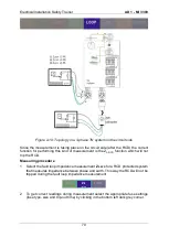
Measuring procedure
1
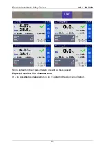
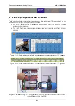
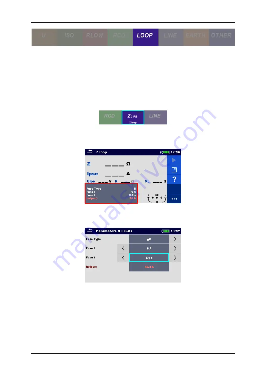
Select the fault loop impedance measurement
Z
L-PE
(
Z loop
) which measures
impedance between phase and earth. When selecting this measurement one must
be sure that a TN system without RCD is used. If a RCD in a TN system is used,
this measurement will cause the RCS to trip. In this case the Z
S
(Z
S RCD
) option
should be considered. It is only possible to perform a Z
LOOP
measurement in a RCD
protected system if the test is done on the supply side as is the case of this
exercise.
2
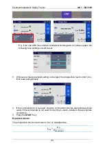
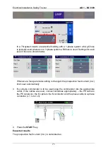
To get correct readings during measurement select the appropriate fuse settings
(fuse type, size and trip-out time) by clicking in the bottom left dark grey corner.
Typically, in a TN system inside a residential building with a 1-phase system a 6A
gG fuse is used.
Whenever a fuse parameter setting is changed, the prospective fault current (I
PSC
)
limit is set automatically.
3
If a schuko commander is to be used, plug the commander into the appropriate
outlet. If the cables are used, connect all cables appropriately
– the PE cable to
the PE conductor, the N cable to the N conductor and the phase cable to a phase
conductor (L1, L2 or L3).
Summary of Contents for MI 3399
Page 27: ...Electrical Installation Safety Trainer AD 1 MI 3399 27...
Page 46: ...Electrical Installation Safety Trainer AD 1 MI 3399 46 3 Exit settings...
Page 74: ...Electrical Installation Safety Trainer AD 1 MI 3399 74...
Page 197: ...Power and Voltage Quality Trainer AD 2 MI 3399 197 Figure 4 89 Transient Chart view...
Page 204: ...PAT Appliances Machines Safety Trainer AD 3 MI 3399 204...
Page 249: ...PV Photovoltaic Systems Trainer AD 4 MI 3399 249...
Page 250: ...PV Photovoltaic Systems Trainer AD 4 MI 3399 250 AD 4 MI 3399 PV Photovoltaic Systems Trainer...

