Electrical Installation Safety Trainer
AD 1 - MI 3399
70
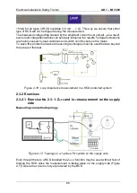
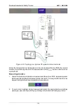
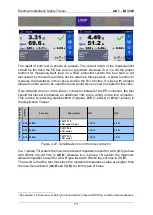
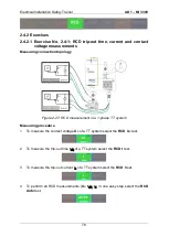
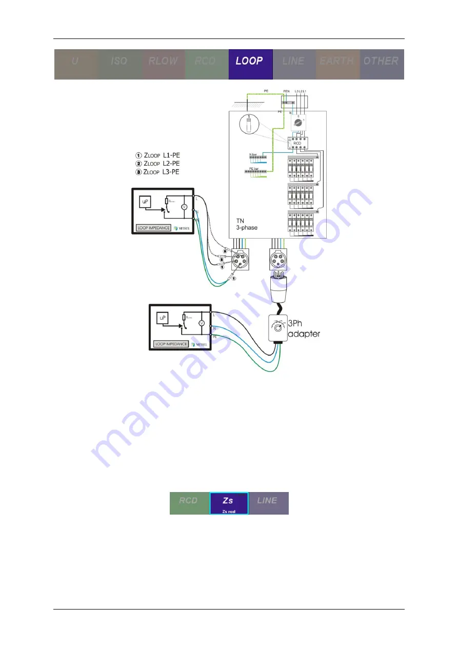
Figure 2-19: Topology in a 3-phase TN system on the circuit side
Since the measurement is taking place on the circuit side (after the RCD) the correct
function for performing this kind of measurement is the Z
S RCD
function which will not
trip the RCD.
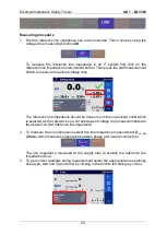
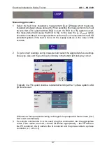
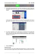
Measuring procedure
1
Select the fault loop impedance measurement
Z
S RCD
for a RCD protected system
that measures impedance between phase and earth. This way the RCD will not be
tripped during the fault loop impedance measurement
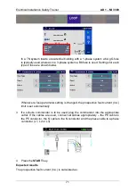
2
To get correct readings during measurement select the appropriate fuse settings
(fuse type, size and trip-out time) by clicking in the bottom left dark grey corner.
Summary of Contents for MI 3399
Page 27: ...Electrical Installation Safety Trainer AD 1 MI 3399 27...
Page 46: ...Electrical Installation Safety Trainer AD 1 MI 3399 46 3 Exit settings...
Page 74: ...Electrical Installation Safety Trainer AD 1 MI 3399 74...
Page 197: ...Power and Voltage Quality Trainer AD 2 MI 3399 197 Figure 4 89 Transient Chart view...
Page 204: ...PAT Appliances Machines Safety Trainer AD 3 MI 3399 204...
Page 249: ...PV Photovoltaic Systems Trainer AD 4 MI 3399 249...
Page 250: ...PV Photovoltaic Systems Trainer AD 4 MI 3399 250 AD 4 MI 3399 PV Photovoltaic Systems Trainer...

