Electrical Installation Safety Trainer
AD 1 - MI 3399
72
𝑰
𝑷𝑭𝑪
=
𝑼
𝑵
𝒁
𝑴𝑬𝑨𝑺𝑼𝑹𝑬𝑫
where:
U
N
– nominal value, determined according to the measured voltage (U
L-PE
).
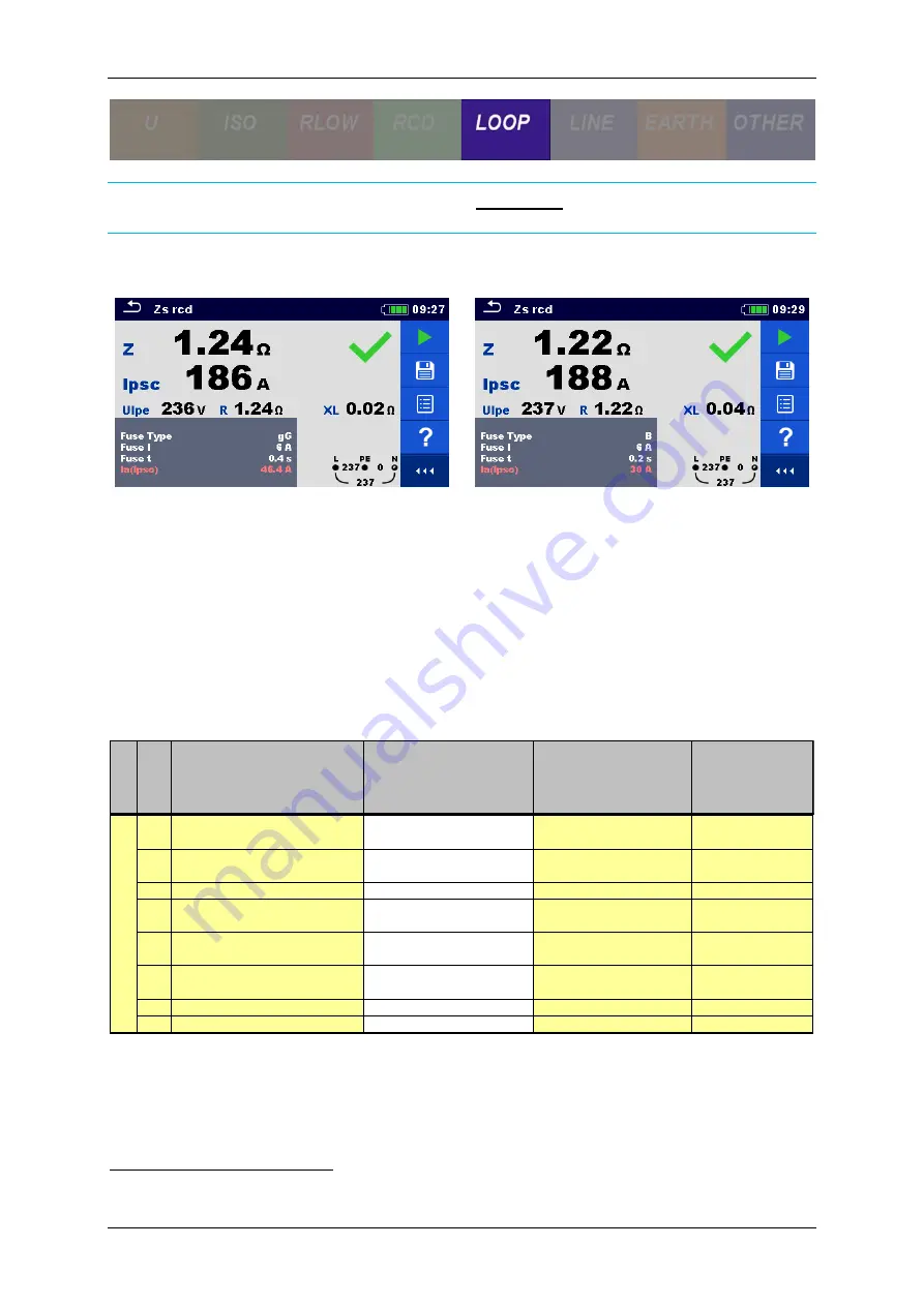
In a 1-phase TN system the maximum allowed impedance result for a 6A gG type fuse
with 400ms trip-out time is
4,6
Ω
whereas in a 3-phase TN system the maximum
allowed impedance result for a 6A B type fuse with 200ms trip-out time is
7,3
Ω
6
.
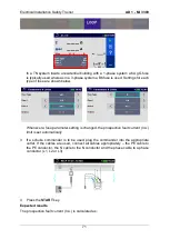
As seen from both screens the impedance and I
PSC
are both within limits and the tests
are marked as passed.
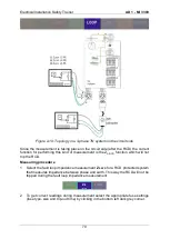
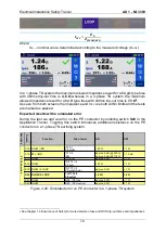
Expected results with a simulated error
During the test we add an error on the PE conductor by enabling switch
S20
in the
Application Trainer. Toggling this switch introduces additional resistance on the PE
conductor on a 1-phase TN earthing system.
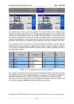
Figure 2-20: Simulated error on PE conductor in a 1-phase TN system
6
See chapter 1.4 Ensurance of Safety for more details on fuse and RCD trip-out times and impedances.
E
xer
ci
ses
S
w
itch
Function
Site of error
ON
OFF
S15 R LOW / IMD
IT F3/1
PE outlet
> 20
Ω
< 1
Ω
S16 ISFL / IMD
IT F3/2
ISFL
approx. 6 mA (@ 230 V)
approx. 3 mA (@ 115 V)
< 1.3 mA
S17 R LOW
IT PE ref.
approx. 3.3 Ω
< 1 Ω
S18 R LOW
TN/TT F1/4
PE light
> 20
Ω
< 1 Ω
S19 R LOW / Z LOOP
TN/TT F1/2
PE outlet (3-ph.)
approx. 3.4 Ω
< 1 Ω
S20 R LOW / Z LOOP
TN/TT F2/2
PE outlet
> 2.3
Ω
< 2 Ω
S21 R LOW
MPE / PE Gas
approx. 2.2 Ω
< 1 Ω
S22 R LOW
MPE / PE Heat inst.
approx. 3.3 Ω
< 1 Ω
P
E
C
o
n
n
e
c
tio
n
Summary of Contents for MI 3399
Page 27: ...Electrical Installation Safety Trainer AD 1 MI 3399 27...
Page 46: ...Electrical Installation Safety Trainer AD 1 MI 3399 46 3 Exit settings...
Page 74: ...Electrical Installation Safety Trainer AD 1 MI 3399 74...
Page 197: ...Power and Voltage Quality Trainer AD 2 MI 3399 197 Figure 4 89 Transient Chart view...
Page 204: ...PAT Appliances Machines Safety Trainer AD 3 MI 3399 204...
Page 249: ...PV Photovoltaic Systems Trainer AD 4 MI 3399 249...
Page 250: ...PV Photovoltaic Systems Trainer AD 4 MI 3399 250 AD 4 MI 3399 PV Photovoltaic Systems Trainer...

