Electrical Installation Safety Trainer
AD 1 - MI 3399
81
2.4.2.2 Exercise No. 2.4-2: RCD trip-out time, current and contact
voltage measurements in an IT earthing system
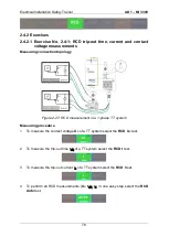
Measuring procedure
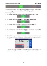
1
To measure the contact voltage
U
C
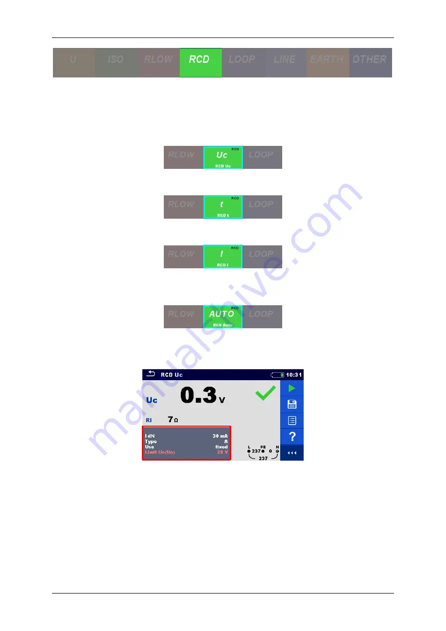
of a IT system select the
RCD U
C
test.
2
To measure the trip-out time
t
ΔN
of a IT system select the
RCD t
test.
3
To measure the trip-out current
I
Δ
of a IT system select the
RCD I
test.
4
To perform all RCD measurements (
U
C
,
t
ΔN
,
I
Δ
) in one easy step select the
RCD
Auto
test.
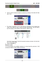
5
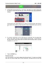
Set the RCD test parameters (I
dN
, current type, selectivity and contact voltage limit)
by clicking in the bottom left dark grey corner and selecting the appropriate RCD
settings.
In this case we use a 30mA RCD so in an IT earthing system which has water
in the proximity. That is why the contact voltage limit must be set to 25 V.
Summary of Contents for MI 3399
Page 27: ...Electrical Installation Safety Trainer AD 1 MI 3399 27...
Page 46: ...Electrical Installation Safety Trainer AD 1 MI 3399 46 3 Exit settings...
Page 74: ...Electrical Installation Safety Trainer AD 1 MI 3399 74...
Page 197: ...Power and Voltage Quality Trainer AD 2 MI 3399 197 Figure 4 89 Transient Chart view...
Page 204: ...PAT Appliances Machines Safety Trainer AD 3 MI 3399 204...
Page 249: ...PV Photovoltaic Systems Trainer AD 4 MI 3399 249...
Page 250: ...PV Photovoltaic Systems Trainer AD 4 MI 3399 250 AD 4 MI 3399 PV Photovoltaic Systems Trainer...

