Electrical Installation Safety Trainer
AD 1 - MI 3399
82
6
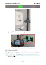
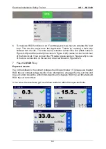
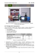
To measure RCD functions in an IT earthing system we have to simulate the fault
loop. This can be achieved in the Application Trainer by creating a fault loop
between two circuits. To create such a situation connect the line (black cable in
Figure 2-26) and the neutral (blue cable in Figure 2-26) cables to Line1 and Line2
of the first circuit. Then connect the PE cable (green cable in Figure 2-26) to one
of the Line conductors on the second circuit as shown in Figure 2-26.
7
Press the
START
key.
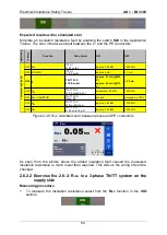
Expected results
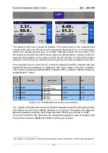
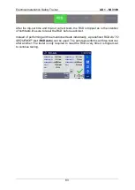
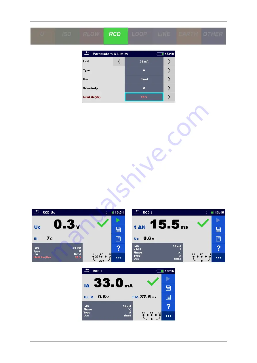
In a normal situation, the contact voltage should be well below 1 V (please see chapter
RCD trip-out contact voltage test for more information), whereas the trip-out time and
trip-out current should be within limits described in chapters RCD trip-out time test and
RCD trip-out current test.
In our case, the results we get for all three tests are within the expected limits.
Summary of Contents for MI 3399
Page 27: ...Electrical Installation Safety Trainer AD 1 MI 3399 27...
Page 46: ...Electrical Installation Safety Trainer AD 1 MI 3399 46 3 Exit settings...
Page 74: ...Electrical Installation Safety Trainer AD 1 MI 3399 74...
Page 197: ...Power and Voltage Quality Trainer AD 2 MI 3399 197 Figure 4 89 Transient Chart view...
Page 204: ...PAT Appliances Machines Safety Trainer AD 3 MI 3399 204...
Page 249: ...PV Photovoltaic Systems Trainer AD 4 MI 3399 249...
Page 250: ...PV Photovoltaic Systems Trainer AD 4 MI 3399 250 AD 4 MI 3399 PV Photovoltaic Systems Trainer...


