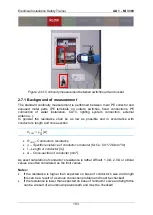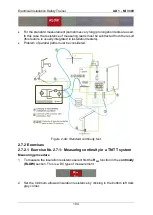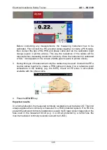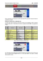
Electrical Installation Safety Trainer
AD 1 - MI 3399
94
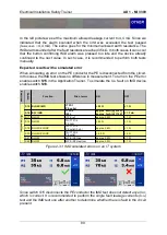
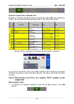
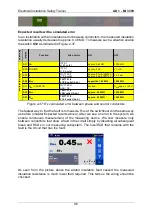
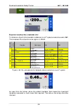
Expected results with a simulated error
Simulate an insulation resistance fault by enabling the switch
S29
in the Application
Trainer. The error introduces a fault between the L1 and the PE conductors.
Figure 2-36: R
ISO
simulated error between phase and PE conductors
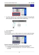
As seen from the picture above the added insulation fault caused the measured
insulation resistance is much lower than required. This tells us the wiring should be
checked.
2.6.2.2 Exercise No. 2.6-2: R
ISO
in a 3-phase TN/TT system on the
supply side
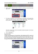
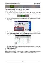
Measuring procedure
1
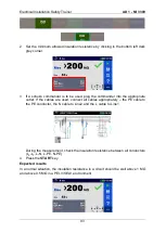
To measure the insulation resistance select first the
R
ISO
function in the
ISO
section.
E
xer
ci
ses
S
w
itch
Function
Site of error
ON
OFF
S27 R
ISO
IT F3/1
L1/L2 outlet
approx. 0.45 MΩ
> 200 M
Ω
S28 ISFL/IMD
IT F3/1
L1/PE outlet
approx. 3 mA
< 1 mA
S29 I
Δ
TN/TT F2/2
L1/PE outlet
approx. 5.1 mA (@230
V)
approx. 2.5 mA (@115
V)
< 3.5 mA
S30 R
ISO
TN/TT F1/2
L1/PE outlet (3-ph.)
capacitive 1.45 MΩ
> 200 M
Ω
S31 R
ISO
/ VARISTOR
TN/TT SPD
GAS / PE
shorted
U
SPD
approx. 150 V
S32 R
ISO
TN/TT F1/2
L2/N outlet (3-ph.)
approx. 0.45 MΩ
> 200 M
Ω
S33 R
ISO
TN/TT F1/2
L1/L2 outlet (3-ph.)
approx. 0.45 MΩ
> 200 M
Ω
In
s
u
la
tio
n
r
e
s
is
ta
n
c
e
Summary of Contents for MI 3399
Page 27: ...Electrical Installation Safety Trainer AD 1 MI 3399 27...
Page 46: ...Electrical Installation Safety Trainer AD 1 MI 3399 46 3 Exit settings...
Page 74: ...Electrical Installation Safety Trainer AD 1 MI 3399 74...
Page 197: ...Power and Voltage Quality Trainer AD 2 MI 3399 197 Figure 4 89 Transient Chart view...
Page 204: ...PAT Appliances Machines Safety Trainer AD 3 MI 3399 204...
Page 249: ...PV Photovoltaic Systems Trainer AD 4 MI 3399 249...
Page 250: ...PV Photovoltaic Systems Trainer AD 4 MI 3399 250 AD 4 MI 3399 PV Photovoltaic Systems Trainer...

