Electrical Installation Safety Trainer
AD 1 - MI 3399
103
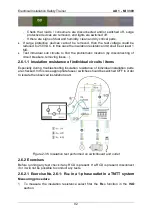
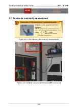
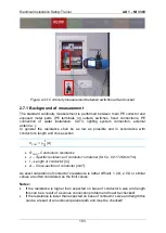
Figure 2-43: Continuity measurement between switchboard and socket
2.7.1 Background of measurement
The standard continuity measurement is performed between main PE collector and
exposed metal parts (PE terminals on outlets, switches, fixed connections, PE
connection of water installation, CATV, lighting system connection, external
antenna...).
In general the resistance shall be as low as possible and in accordance with
conductor’s length and cross-section.
𝑅
𝐶𝑂𝑁
= ρ
l
A
[Ω]
R
CON
– Conductor’s resistance
ρ
– Specific resistance of conductor’s material (for Cu: 0.0172 Ωmm
2
/m)
l
– Length of conductor [m]
A
– Cross-section of conductor [mm
2
].
As exact calculation of conductor’s resistance is rather difficult, 1.0 Ω, 2.0 Ω or similar
values are often considered as the limit values.
Notes:
If the resistance is higher than expected on base of conductor’s size and length
this can be a result of a serious connection problem and must be checked!
If the resistance is lower than expected on base of conductor’s size and length this
can be a result of an unknown parallel path and must be checked!
Summary of Contents for MI 3399
Page 27: ...Electrical Installation Safety Trainer AD 1 MI 3399 27...
Page 46: ...Electrical Installation Safety Trainer AD 1 MI 3399 46 3 Exit settings...
Page 74: ...Electrical Installation Safety Trainer AD 1 MI 3399 74...
Page 197: ...Power and Voltage Quality Trainer AD 2 MI 3399 197 Figure 4 89 Transient Chart view...
Page 204: ...PAT Appliances Machines Safety Trainer AD 3 MI 3399 204...
Page 249: ...PV Photovoltaic Systems Trainer AD 4 MI 3399 249...
Page 250: ...PV Photovoltaic Systems Trainer AD 4 MI 3399 250 AD 4 MI 3399 PV Photovoltaic Systems Trainer...

