Electrical Installation Safety Trainer
AD 1 - MI 3399
104
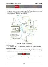
For the standard measurement (sometimes very long) prolongation tests are used.
In this case the resistance of measuring leads must be subtracted from the result
(this feature is usually integrated in installation testers).
Problem of parallel paths must be considered.
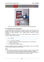
Figure 2-44:
Standard continuity test
2.7.2 Exercises
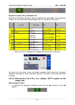
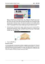
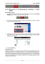
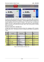
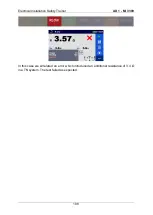
2.7.2.1 Exercise No. 2.7-1: Measuring continuity in a TN/TT system
Measuring procedure
1
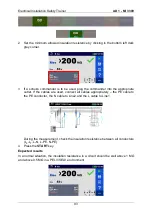
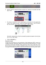
To measure the insulation resistance select first the
R
200
function in the
continuity
(RLOW)
section. This is a DC type of measurement.
2
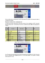
Set the minimum allowed insulation resistance by clicking in the bottom left dark
grey corner.
Summary of Contents for MI 3399
Page 27: ...Electrical Installation Safety Trainer AD 1 MI 3399 27...
Page 46: ...Electrical Installation Safety Trainer AD 1 MI 3399 46 3 Exit settings...
Page 74: ...Electrical Installation Safety Trainer AD 1 MI 3399 74...
Page 197: ...Power and Voltage Quality Trainer AD 2 MI 3399 197 Figure 4 89 Transient Chart view...
Page 204: ...PAT Appliances Machines Safety Trainer AD 3 MI 3399 204...
Page 249: ...PV Photovoltaic Systems Trainer AD 4 MI 3399 249...
Page 250: ...PV Photovoltaic Systems Trainer AD 4 MI 3399 250 AD 4 MI 3399 PV Photovoltaic Systems Trainer...

