Power and Voltage Quality Trainer
AD 2
– MI 3399
139
In practice, when connecting the instrument to the electrical system, it is essential that
both current and voltage connections are correct. In particular the following rules have
to be observed:
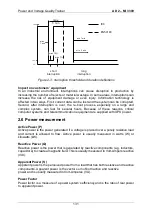
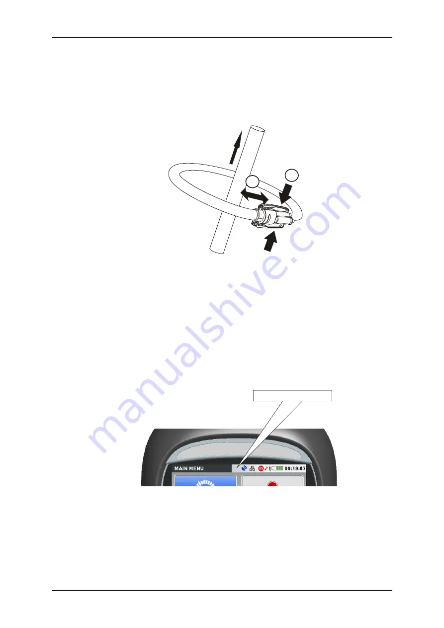
Clamp-on current clamp-on transformers
The arrow marked on the clamp-on current transformer should point in the
direction of current flow, from supply to load.
I
1
2
If a clamp-on current transformer is connected in reverse the measured power
in that phase would normally appear negative.
Phase relationships
The clamp-on current transformer connected to the current input connector I
1
has to measure the current in the phase line to which the voltage probe from L
1
is connected.
3.3
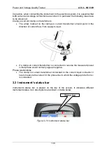
Instrument’s status bar
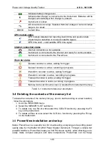
Instruments status bar is placed on the top of the screen. It indicates different
instrument states. Icon descriptions are shown on table below.
Status bar
Figure 3-10: Instrument status bar
Summary of Contents for MI 3399
Page 27: ...Electrical Installation Safety Trainer AD 1 MI 3399 27...
Page 46: ...Electrical Installation Safety Trainer AD 1 MI 3399 46 3 Exit settings...
Page 74: ...Electrical Installation Safety Trainer AD 1 MI 3399 74...
Page 197: ...Power and Voltage Quality Trainer AD 2 MI 3399 197 Figure 4 89 Transient Chart view...
Page 204: ...PAT Appliances Machines Safety Trainer AD 3 MI 3399 204...
Page 249: ...PV Photovoltaic Systems Trainer AD 4 MI 3399 249...
Page 250: ...PV Photovoltaic Systems Trainer AD 4 MI 3399 250 AD 4 MI 3399 PV Photovoltaic Systems Trainer...

