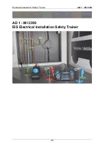
Electrical Installation Safety Trainer
AD 1 - MI 3399
36
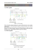
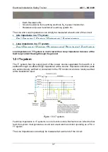
In TN-C-S systems exposed conductive parts are partly connected to the PE conductor
and partly to the PEN conductor.
All line conductors are fuse protected. The earthing resistance is usually low enough
because of low PEN and PE conductor resistance and good earthing at the source and
distribution points. Additional RCD protection can be applied where N and PE
conductors are separated.
The Line and Loop Impedances can simply be measured at each end of the circuit:
Line impedance in a TN system:
Z
Line
= Z
Line conductor
+ Z
Transformer
+ Z
Neutral conductor
+ Z
Local neutral conductor
Loop impedance in a TN system:
Z
Loop
= ZL
ine conductor
+ Z
Transformer
+ Z
Neutral conductor
+ Z
Local PE conductor
In case the continuity is good for all conductors
– Line, Neutral and PE – then
Line and Loop Impedance in TN system are basically the same.
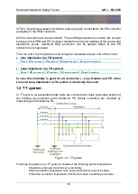
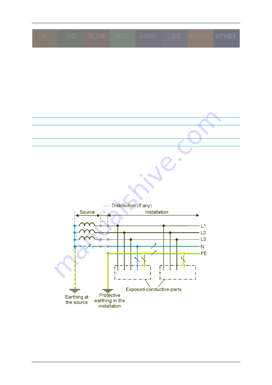
1.2 TT system
In TT system, all accessible metal parts are connected to basic grounding system of
the building via protection earth conductor PE. Safety conditions are checked by
measuring earth resistance R
E
.
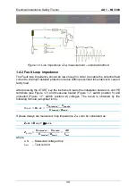
Figure 1-4: TT system
Fault loop impedance in a TT system consists of the following partial impedances:
-
Impedance of power transformer’s secondary.
-
Phase conductor impedance from power transformer to fault location.
-
Protection conductor impedance from fault location to earthing electrode.
Summary of Contents for MI 3399
Page 27: ...Electrical Installation Safety Trainer AD 1 MI 3399 27...
Page 46: ...Electrical Installation Safety Trainer AD 1 MI 3399 46 3 Exit settings...
Page 74: ...Electrical Installation Safety Trainer AD 1 MI 3399 74...
Page 197: ...Power and Voltage Quality Trainer AD 2 MI 3399 197 Figure 4 89 Transient Chart view...
Page 204: ...PAT Appliances Machines Safety Trainer AD 3 MI 3399 204...
Page 249: ...PV Photovoltaic Systems Trainer AD 4 MI 3399 249...
Page 250: ...PV Photovoltaic Systems Trainer AD 4 MI 3399 250 AD 4 MI 3399 PV Photovoltaic Systems Trainer...

