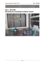
Electrical Installation Safety Trainer
AD 1 - MI 3399
38
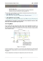
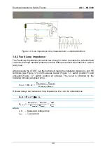
Line impedance in an IT system:
Z
Line
= Z
Line conductor
+ Z
Transformer
+ Z
Neutral conductor
+ Z
Local neutral conductor
Loop impedance in an IT system:
Z
Loop
= OPENED LOOP (results are in the high range, usually over 35 kOhm)
All line conductors are fuse protected. IMDs and RCMs are often installed in an IT
system to detect insulation faults and to trigger an alarm before the supply must be
disconnected. RCDs are only partly applicable.
IT systems are usually installed in:
Medical surgery rooms and hospitals.
Emergency lighting in communal facilities.
Emergency vehicles (fire trucks, ambulance vehicles,
…) where the PE
conductor is connected to the chassis of the vehicle itself.
Ships.
Computer power supply systems.
Chemical industry.
Mining industry.
Explosive atmospheres, chemical industry
2
.
The main advantage is that in case of the first fault (between phase and earth) the
system still works safely.
1.4 Ensurance of Safety
1.4.1 Line impedance
The Line impedance result between the line and neutral conductor can show the ability
of the built in conductors to supply the high power loads. Verification of installed over-
current breakers is possible by comparing the characteristics with calculated short
circuit current.
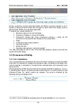
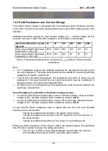
After pressing the START key the instrument loads the installation between L, N or L
x
,
L
y
terminals (see Figure 1-6) and measures loaded (Figure 1-6: switch position
1
) and
unloaded (Figure 1-6: switch position
2
) voltages. The result is obtained by the
following formula (simplified form).
𝑍
𝐿𝐼𝑁𝐸
= 𝒁
𝑳𝑵
=
𝑼
𝑼𝒏𝒍𝒐𝒂𝒅𝒆𝒅
− 𝑼
𝑳𝒐𝒂𝒅𝒆𝒅
𝑼
𝑳𝒐𝒂𝒅𝒆𝒅
/𝑹
𝑳𝒐𝒂𝒅
2
See Metrel’s Handbook
Guide for measurements on IT power installation
for more information.
Summary of Contents for MI 3399
Page 27: ...Electrical Installation Safety Trainer AD 1 MI 3399 27...
Page 46: ...Electrical Installation Safety Trainer AD 1 MI 3399 46 3 Exit settings...
Page 74: ...Electrical Installation Safety Trainer AD 1 MI 3399 74...
Page 197: ...Power and Voltage Quality Trainer AD 2 MI 3399 197 Figure 4 89 Transient Chart view...
Page 204: ...PAT Appliances Machines Safety Trainer AD 3 MI 3399 204...
Page 249: ...PV Photovoltaic Systems Trainer AD 4 MI 3399 249...
Page 250: ...PV Photovoltaic Systems Trainer AD 4 MI 3399 250 AD 4 MI 3399 PV Photovoltaic Systems Trainer...

