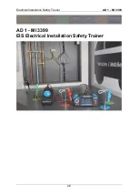
Electrical Installation Safety Trainer
AD 1 - MI 3399
39
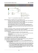
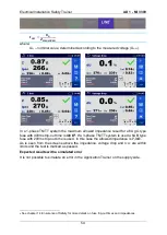
Figure 1-6: Line impedance (Z
LN
) measurement
– standard method
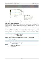
1.4.2 Fault Loop impedance
The Fault loop impedance should be low enough in order to enable the potential fault
current to interrupt installed protection device within prescribed time interval in case of
faulty load.
After pressing the START key the instrument loads the installation between L and PE
terminals (see Figure 1-7) and measures loaded (Figure 1-7: switch position
1
) and
unloaded (Figure 1-7: switch position
2
) voltages. The result is obtained by the
following formula (simplified form).
𝑅
𝐿𝑂𝑂𝑃
= 𝑹
𝑳−𝑷𝑬
=
𝑼
𝑼𝒏𝒍𝒐𝒂𝒅𝒆𝒅
− 𝑼
𝑳𝒐𝒂𝒅𝒆𝒅
𝑼
𝑳𝒐𝒂𝒅𝒆𝒅
/𝑹
𝑳𝒐𝒂𝒅
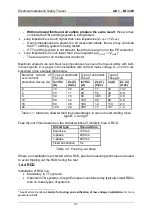
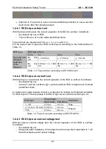
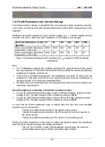
If phase delays are measured, loop impedance Z
L-PE
can be calculated as:
Z
L-PE
= R
L-PE
+ j
L
L-PE
𝒁
𝑳−𝑷𝑬
=
𝑼
𝑼𝒏𝒍𝒐𝒂𝒅𝒆𝒅
− 𝑼
𝑳𝒐𝒂𝒅𝒆𝒅
𝑼
𝑳𝒐𝒂𝒅𝒆𝒅
/𝑹
𝑳𝒐𝒂𝒅
=
𝜟𝑼
𝑰
𝒕𝒆𝒔𝒕
where
Δ
U
– Measured voltage drop
I
test
– Test current
Summary of Contents for MI 3399
Page 27: ...Electrical Installation Safety Trainer AD 1 MI 3399 27...
Page 46: ...Electrical Installation Safety Trainer AD 1 MI 3399 46 3 Exit settings...
Page 74: ...Electrical Installation Safety Trainer AD 1 MI 3399 74...
Page 197: ...Power and Voltage Quality Trainer AD 2 MI 3399 197 Figure 4 89 Transient Chart view...
Page 204: ...PAT Appliances Machines Safety Trainer AD 3 MI 3399 204...
Page 249: ...PV Photovoltaic Systems Trainer AD 4 MI 3399 249...
Page 250: ...PV Photovoltaic Systems Trainer AD 4 MI 3399 250 AD 4 MI 3399 PV Photovoltaic Systems Trainer...

