background image

Installation Guide     11

Apply Power

Power is applied to the “twister” through the desktop power supply. To
apply power, do the following:

1. Connect the power cord (not included with international shipments) to

the AC receptacle on the power supply.

2. Connect the power supply to the DC input power jack located on the

back of the “twister”.

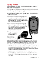
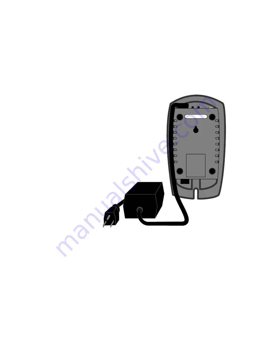
3. The “twister” is designed with built-in cable

management and protection. Turn the unit
upside-down and route the DC power cord
into one of the two channels located on each
side of the unit. See diagram.

4. Plug the power cord into an AC wall outlet.

Upon receiving power, the power (PWR)
LED turns green, and the “twister” automati-
cally goes into operation providing the
appropriate signal translation between
connected network segments.

5. Verify valid connections via

the link (LK) LEDs,
which should be lit.

If an additional
extension cord is
needed to connect the
power supply to the outlet, use the guidelines below. While one end of
the AC power cord can be fitted with a plug standard for the country of
operation, the end that connects to the Metrobility power supply must
have a female plug that fits the following type of AC receptacle:

AC 115V (North America): Use a UL-listed and CSA-certified cord set
consisting of a minimum of No. 18 AWG, type SVT or SJT three-
conductor cord (5 feet maximum length) and a parallel blade ground-
ing-type attachment plug rated 15A, 125V.

AC 230V (USA): Use a UL-listed cord set consisting of a minimum
No. 18 AWG, type SVT three-conductor cord (15 feet maximum
length) and a Tandem blade grounding-type attachment plug rated
15A, 250V.

Summary of Contents for Delta Class

Page 1: ...Installation and User s Guide twister M133 ACT FD ACT LK PWR METRO bility optical systems LK FEF LB FAIL LB PASS 100Mbps twister...

Page 2: ...nd current The manufacturer is not responsible for errors or omissions and reserves the right to change specifications at any time without notice This manual covers the following Metrobility 100Mbps D...

Page 3: ...hoose an Appropriate Location 5 Set the Switches 6 Connect to the Network 8 Apply Power 11 User s Guide 13 LED Indicators 13 Link Loss Carry Forward LLCF 14 Far End Fault FEF 16 Remote Loopback 17 Top...

Page 4: ...throughout the network The twister incorporates both Far End Fault and Link Loss Carry Forward two troubleshooting functions to help identify the loss of a remote network connection On select models b...

Page 5: ...ipped with four rubber feet located on the black adhesive strip To install the rubber feet first turn the twister upside down Peel the feet from the adhesive strip then attach one foot to each circula...

Page 6: ...ctionality as an aid in troubleshooting remote connections When LLCF is enabled the loss of inbound link pulses on a port stops the transmission of outbound link pulses on the opposite port For exampl...

Page 7: ...the duplex switch will determine the port s duplex mode By default auto negotiation is enabled Duplex Switch FD1 Switch FD1 sets the duplex mode for the copper port when auto negotia tion is disabled...

Page 8: ...emote unit and then looped back The local twister will read the returned data to verify proper transmission The LB LED on the local twister will indicate whether the test passed green or failed amber...

Page 9: ...The M133 14 16 and 1M provide one set of FX singlemode SC ST LC connectors respectively and support a segment length of up to 20km for remote links The M133 17 provides one set of FX singlemode SC co...

Page 10: ...pports a maximum segment length of 20km BWDM line cards must always be used in complementary pairs That is a 1X model must be connected to a 1Y The 1X cards are designed to transmit data at a waveleng...

Page 11: ...he appropriate signal translation between connected network segments 5 Verify valid connections via the link LK LEDs which should be lit If an additional extension cord is needed to connect the power...

Page 12: ...outside USA Use a cord set consisting of a minimum No 18 AWG cord and grounding type attachment plug rated 15A 250V The cord set should have the appropriate safety approvals for the country in which t...

Page 13: ...o p e h t t a h t s e i f i r e V T C A y t i v i t c a g n i h s a l f n e e r g a t a d g n i v i e c e r s i t r o p e h T s D E L t r o P r e b i F B L S S A P k c a b p o o l s s a p y d a e t s...

Page 14: ...er LED lit established link LED unlit no link LLCF is ON LLCF is ON Remote Cable If a connection breaks each twister will carry that link loss forward to a switch hub which generates a trap to a manag...

Page 15: ...ter units to establish link local twister remote twister LED lit established link LED unlit no link LLCF is ON LLCF is ON Fiber Cable Copper Cable Copper Cable AN is ON AN is ON AN is ON AN is ON As c...

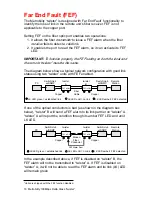
Page 16: ...e of the optical conductors is bad as shown in the diagram box below twister B will send a FEF alarm to its link partner on twister A twister A will report the condition through its amber FEF LED and...

Page 17: ...remote unit goes into loopback mode in which the fiber port returns the incoming traffic back to the sender The local twister generates a test pattern that is sent to the remote port and then looped b...

Page 18: ...n less than 15 seconds Time Out Indications D E L L I A F B L l a c o L D E L L I A F B L e t o m e R r o l o C s u t a t s n o i t a c i d n I r o l o C s u t a t s n o i t a c i d n I r e b m A f e...

Page 19: ...Switch F O Links Twisted pair Links 100Mbps Switch 100Mbps Switch 2km multimode F O 2km multimode F O 20km singlemode F O Servers with 100Mbps NICs Metrobility M133 Metrobility M133 Metrobility M133...

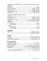
Page 20: ...m ________________ 20 dBm to 14 dBm 62 5 125 m Supported Link Length ______________________ up to 2km full duplex Cable Type ____________________________50 125 62 5 125 m F O Singlemode Fiber Optic I...

Page 21: ...nd F O M133 1X TX Wavelength ___________________________________ 1550nm RX Wavelength ___________________________________ 1310nm M133 1Y TX Wavelength ___________________________________ 1310nm RX Wav...

Page 22: ...ts are designed to provide reasonable protection against harmful interfer ence when the equipment is operated in a commercial environment This equipment generates uses and can radiate radio frequency...

Page 23: ...fective product for warranty coverage contact Metrobility Customer Service for a return materials authorization RMA number Send the defective product postage and insurance prepaid to the ad dress prov...

Page 24: ...obtain additional copies of this manual contact your reseller or call 1 877 526 2278 or 1 603 880 1833 Product Registration To register your product go to http www metrobility com support registration...

Reviews: