background image

12

  Installation Guide

3

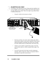
Insert the card into a slot on the chassis making sure that the
top and bottom edges of the board are aligned with the top and
bottom card guides in the chassis. Do not force the card into
the chassis unnecessarily. It should slide in easily and evenly.

Slide the card in until the top and bottom edges of the front
panel are flush and even with the top and bottom edges of the
chassis.

To secure the line card to the chassis, turn the thumbscrew
clockwise until it is snug. The card is now properly installed
and ready for connection to the network.

FX

PWR

RX

RX

LK

LK

M
M

FL

TX

TX

10/100

M
M

RX

LK

TX

FX

M
M

II

x

PWR

100

FD

RX

LK

T
X

TX

10/100

II

x

PWR

100

FD

RX

RX

LK

LK

T
X

M
M

FL

TX

TX

10/100

II

x

II

x

PWR

100

FD

100

FD

RX

RX

LK

LK

T
X

T
X

TX

TX

10/100

RX

LK

TX

FX

M
M

II

x

PWR

100

FD

RX

LK

T
X

TX

10/100

MGT-10

LK

AT

C
O
N
S
O
L
E

1

PWR

A

B

R

ER

FX

PWR

RX

RX

LK

LK

M
M

FL

TX

TX

10/100

M
M

PWR

RX

RX

LK

LK

M
M

FL

TX

TX

10/100

FX

M
M

PWR

M
M

OC-12

R
X

LK

LK

T
X

S
M

R
X

T
X

LX

LK

LK

PWR

1000BASE

S
M

SX

M
M

PWR

1000BASE

LK

LK

SX

M
M

LX

S
M

R
X

T
X

Card Guide

Card Guide

Slot for Management Card

Thumb Screw

Blank Panel

IMPORTANT!

Tighten thumb screw

to secure each card firmly

to chassis before making

network connections.

FX

PWR

RX

RX

LK

LK

M
M

FL

TX

TX

10/100

M
M

FX

PWR

RX

RX

LK

LK

M
M

FL

TX

TX

10/100

M
M

PWR

M
M

OC-12

R
X

LK

LK

T
X

S
M

R
X

T
X

PWR

M
M

OC-12

R
X

LK

LK

T
X

S
M

R
X

T
X

PWR

M
M

OC-12

R
X

LK

LK

T
X

S
M

R
X

T
X

PWR

M
M

OC-12

R
X

LK

LK

T
X

S
M

R
X

T
X

R
X

T
X

LK

PWR

M
M

10/100

LK

M
M

FL

FX

RX

TX

RX

TX

LK

AT

2

Install the Line Card

The Radiance line card offers the ease of plug-and-play installation and
is hot-swappable. The card must be firmly secured to the chassis before
network connections are made. Follow the simple steps outlined below
to install your line card.

Grasp the card by the front panel as shown.

Summary of Contents for R611-51

Page 1: ...100 RX LK TX FX M M II x PWR 100 FD RX LK T X TX 10 100 RX LK TX FX M M II x PWR 100 FD RX LK T X TX 10 100 PWR RX RX LK LK M M FL TX TX 10 100 FX M M II x PWR 100 FD RX RX LK LK T X M M FL TX TX 10...

Page 2: ...41 13 ____ 10 100Base TX to 100Base FX multimode SC R641 14 ____ 10 100Base TX to 100Base FX singlemode SC R641 15 ____ 10 100Base TX to 100Base FX multimode ST R641 17 ____ 10 100Base TX to 100Base F...

Page 3: ...Specifications 20 Product Safety EMC and Compliance Statements 22 Warranty and Servicing 23 Metrobility Metrobility Optical Systems AutoTwister and NetBeacon are registered trademarks of Metrobility...

Page 4: ...station The Radiance 10 100Mbps interface line cards offer the following key features Auto negotiation switches on all twisted pair interfaces Link Loss Return LLR functionality to aid in troubleshoot...

Page 5: ...he following conversion combinations 10 100Base TX to 10 100 Base TX 10 100Base TX to 100Base FX multimode SC 10 100Base TX to 100Base FX singlemode SC 10 100Base TX to 100Base FX multimode ST 10 100B...

Page 6: ...o eliminate the need for crossover cables the Radiance 10 100Mbps interface line card includes an MDI II to MDI X switch on each twisted pair port This push in switch is located in the center of the f...

Page 7: ...I x PWR 100 FD RX RX LK LK TX TX 10 100 DIP switches Power Connector Port 1 MDI II to MDI X Switch Port 2 When setting DIP switches the UP position is when the lever of the DIP switch is pushed away f...

Page 8: ...en auto negotiation is enabled If auto negotiation is disabled the port speed is the same as the switch setting where UP is 100Mbps and DOWN is 10Mbps When the 100M switch is UP the port advertises 10...

Page 9: ...disabled on both ports Refer to Link Loss Return in the User Guide section of this manual for more detailed information Link Loss Carry Forward Switch LLCF In addition to LLR the R612 51 and R642 xx u...

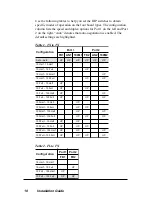
Page 10: ...H 0 0 1 l l u F 0 1 P U P U l l u F 0 0 1 l l u F 0 1 P U P U P U f l a H 0 1 f l a H 0 0 1 P U l l u F 0 1 f l a H 0 0 1 P U P U f l a H 0 0 1 f l a H 0 0 1 P U P U l l u F 0 0 1 f l a H 0 0 1 P U P...

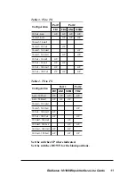
Page 11: ...l a H 0 0 1 l l u F 0 0 1 P U P U l l u F 0 0 1 l l u F 0 0 1 P U P U P U Table 3 FL to TX Table 4 TX to FX Set the switches UP where indicated Set the switches DOWN for the blank positions n o i t a...

Page 12: ...00 MGT 10 LK AT C O N S O L E 1 PWR A B R ER FX PWR RX RX LK LK M M FL TX TX 10 100 M M PWR RX RX LK LK M M FL TX TX 10 100 FX M M PWR M M OC 12 R X LK LK T X S M R X T X LX LK LK PWR 1000BASE S M SX...

Page 13: ...E 1 1 4 6 R 5 4 J R J R T M e d o m i t l u m X F G 1 1 4 6 R 5 4 J R 5 4 F V e d o m i t l u m X F 1 5 1 1 6 R 1 5 2 1 6 R T S e d o m i t l u m L F 5 4 J R 3 5 1 4 6 R 3 5 2 4 6 R T S e d o m i t l...

Page 14: ...X TX 10 100 FX RX LK TX M M II x PWR 100 FD RX LK T X TX 10 100 MGT 10 LK AT C O N S O L E 1 PWR A B R ER FX PWR RX RX LK LK M M FL TX TX 10 100 M M PWR RX RX LK LK M M FL TX TX 10 100 FX M M LK AT 2...

Page 15: ...l o C n o i t c n u F R W P r e w o p y d a e t s n e e r G y l l a m r o n g n i n o i t c n u f d n a N O s i t i n u e h T K L k n i l y d a e t s n e e r G k n i l d i l a v a s a h t r o p e h t...

Page 16: ...pattern to force a collision on a port if the line card cannot allocate a buffer for the port s incoming packets Activating backpressure enables it for both ports Backpressure is ignored in full dupl...

Page 17: ...are shipped with the LLR function disabled DOWN PC Remote Station Switch Hub w SNMP Switch Hub w SNMP Radiance Line Card Fiber Cable LED lit established link LED unlit no link LLR is OFF LLR is ON Ra...

Page 18: ...he switch hubs which generate a trap to the management stations A network administrator can then determine the source of the problem Link Loss Carried Forward Link Loss Carried Forward LED lit establi...

Page 19: ...ir Links 10 100Mbps Hub Radiance Central Service Platform with 10 100Mbps Line Cards AutoTwister Servers with 100Mbps NICs 10Mbps Workgroup Hub copper or fiber FDX 2km mm fiber 2km mm fiber 20km 40km...

Page 20: ...dBm 50 125 m ______________________ 14 dBm to 20 dBm 62 5 125 m Supported Link Length ___________________________ up to 2 km full duplex Cable Type ________________________________ 50 125 or 62 5 125...

Page 21: ...plex 200 Mbps full duplex Fast Ethernet _____________10 Mbps half duplex 20 Mbps full duplex Ethernet Latency _____________________________________ 9 s 100 Mbps input _________________________________...

Page 22: ...o provide reasonable protection against harmful interference when the equip ment is operated in a commercial environment This equipment generates uses and can radiate radio frequency energy and if not...

Page 23: ...of purchase To return a defective product for warranty coverage contact Metrobility Customer Service for a return materials authorization RMA number Send the defective product postage and insurance p...

Page 24: ...e at http www metrobility com support manuals htm Product Registration To register your product go to http www metrobility com support registration asp 25 Manchester Street Merrimack NH 03054 USA tel...

Reviews: